- Details
-
Category: Quickie Plans
-
Published: Thursday, 23 October 2008 01:00
-
Written by Dan Yager
-
Hits: 3760
BASIC AILERON CONSTRUCTION
Both ailerons can be constructed together to save time. These instructions will only cover the construction of the left aileron, but the right one is a mirror image.
Begin by rounding up CS9, which is a 3 ft. length of 1” O.D. x .035” wall 2024T3 Aluminum tubing. You have already hot-wired the Inboard and Outboard Aileron foam cores, so gather those together also. The inboard aileron foam core should be trimmed to 36" length; the outboard core should be trimmed to a 6” length.
Basically, you will join CS9 to the inboard core; join the outboard core to that combination; sand the leading edge to remove bumps and joggles; layup the bottom skin; layup the top skin; and finally trim the trailing edge after installation.
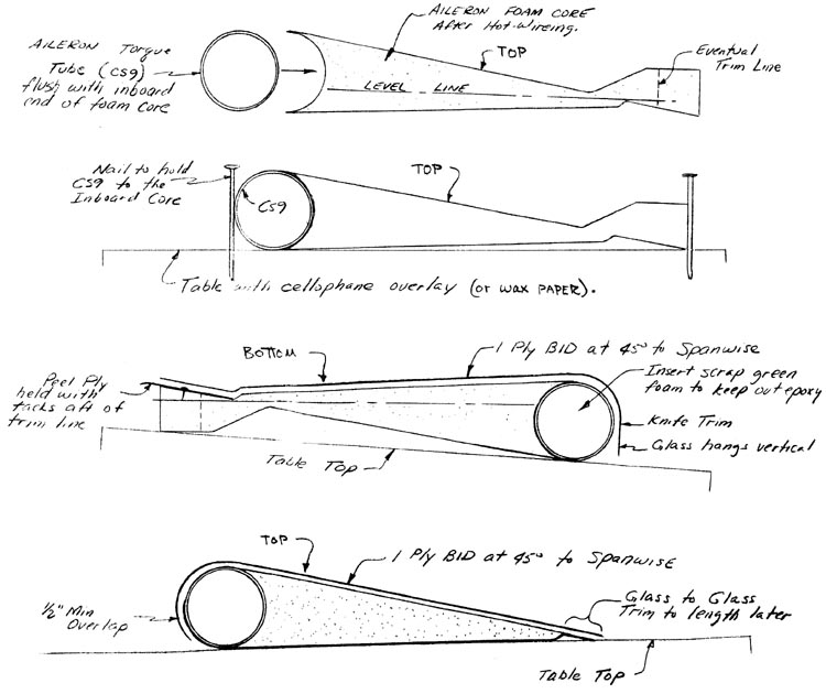
Begin by sanding CS9 to remove grease, finger prints, and the oxidation layer on the aluminum. Fit CS9 to the inboard foam core; mix up some micro slurry, and join CS9 to the inboard core on a flat surface. Use nails to hold the two pieces together.
After this combination has cured, join the outboard foam core to the outboard end of the CS9-core combination with micro slurry. Grey tape can be used to help hold it tight against the inboard core.
Once this combination has cured, you are ready to glass the bottom skin after sanding away all of the bumps and joggles. Turn the aileron over and lay it flat on the table. Put Peel Ply along the trailing edge by using small tacks to hold it in place. Layup one ply BID at 45 deg. to the trailing edge. At the leading edge, let it drop vertically to the table. Cut the trailing edge past the “eventual trim line” that is called out.
When this layup has cured, turn the aileron over and lay it flat upon the table. At the leading edge, feather the BID ply to the foam to remove the joggle. At the trailing edge, sand off the “tail” until you reach the Peel Ply. Remove the Peel Ply, and the aileron is ready to glass. Layup one ply BID at 45 deg. to the trailing edge. At the leading edge overlap a minimum of 0.5”. At the trailing edge, layup glass to glass. Leave the aileron alone until after curing to avoid tampering with the alignment.
Leave the trailing edge untrimmed until after the aileron is mounted on the main wing.


