Login Form

Q1 Plans Chapter 20 Page 20-1

LARGE WHEEL PANT CONSTRUCTION

Chapter 20 covers the making and installation of the optional large diameter wheel pants and tires as well as the necessary modifications to the tailwheel assembly.

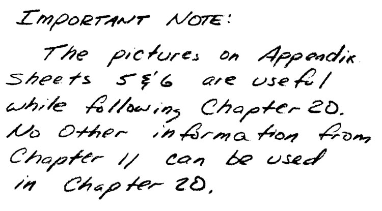
As such, Chapter 20 replaces Chapter 11, Appendix Sheets 5 & 6, and modifies Page 8-5. Therefore, the above pages should not be used for any construction information unless specifically referred to by this Chapter 20.


In this section, you will make one left wheel pant and one right wheel pant.

The wheel pants are composite structural shapes that must carry all landing gear loads into the canard. Therefore, they are made much stronger than the ordinary cosmetic type wheel pants found on many homebuilts. There is some carving required, but after having finished the fuselage, you will find that easy.

Begin by making two each LG10 LG11, nd LG12. LG11 and LG12 are made from the orange foam. The LG10 cores are made from the blue foam. Mark one set Left and one set Right to avoid confusion.

The following procedure will be used to make the left wheel pant. However, the right wheel pant is just a mirror image so that the same basic instructions will cover it also. You will probably find it easier to do both of them at the same time.
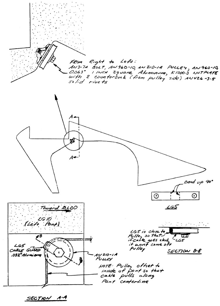

Quickie Large Wheel Pant Pulley Detail

Use a piece of O.O63”, thick aluminum one inch square, drill a hole for an AN3 bolt in the center, and then rivet a nutplate to the aluminum so that the bolt can pass through the aluminum into the nutplate. Assemble the pulley combination as shown. Next, trial fit the assembly in the LG10 core, removing foam so that the aluminum will fit flush with the LG10 face. When satisfied, remove the pulley and bolt, protect the nutplate hole with silicone, and mount the aluminum/nutplate assembly to LG10 with flox.

Q1 Plans Chapter 20 Page 20-2

LARGE WHEEL PANT CONSTRUCTION

Next, you will need to Join LG12 with micro. Remember that the LG12 goes on the inboard face of LG10 (i.e. as you visualize the wheel pant mounted on the canard, LG12 is on the same side of the LG10 as the fuselage is). Leading edge and trailing edge marks have been included on the LG1O sketch to allow you to line up the pieces; basically, LG12 covers up the LG10 cutout. You may need to use some weight to hold the pieces to gether until they have cured.

Once that curing is accomplished lay the combination on the table with LG12 face down, and layup two plies of BID on the inside of LG12 allowing the cloth to lap up on the LG10 faces that surround LG12

Quickie Large Wheel LG10 and LG12 Detail

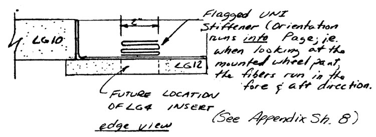
Now, you are ready to flag the UNI stiffener over the location of the LG4 inserts. Begin with a piece of UNI cloth 10” x7” with the orientation along the 7” edge. Flag the piece 5 times along the “7” edge(i.e. every 2”). Flagging consists of the following procedure:

  1. Fold the cloth over on itself
  2. Wet out the cloth
  3. Lightly run a new razor blade across the bubble
  4. Stipple the cloth down
  5. Repeat steps 1-4 as many times as needed. (5 times)
Quickie Large Wheel Pant UNI Stiffener Detail

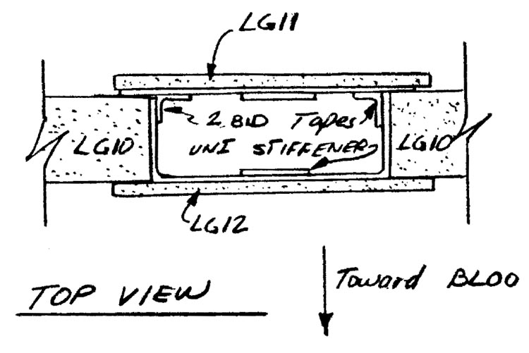
While the layup is curing, take LG11 and layup two BID on the inside face (i.e. the face that will be inside the LG10 cut out when it is attached.) Roughly trim the glass so that it doesn’t extend beyond the edges of LG11, but don’t be concerned If you trim somewhat inside the edges. Flag a UNI stiffener to LG11 just like you did with LG12, remembering that the stiffener is on the side of. LG11 that will be inside the LG10 cutout when LC11 is joined to LG10.

While the LG11 layup is still tacky, join LG11 to LG10 with micro. Now, layup two BID tapes on the inside to join the LG11 glass layup to the LG10 glass.

At this point, you should have a sandwich, with LG10 as the core, LG11 as the outboard face, and LG12 as the inboard face.

Drill in the pulley hole with a short angle drill. If you dont have one, cut the hole with a small exacto knife.

Quickie Large Wheel Pant LG11 Detail

Next, the two LG4 inserts must be placed into postition after the previous layups have cured. Remove orange foam from LG11 and LG12 down to the inside glass layup in the areas on the LG11 and LG12 patterns which denote the locations of the LG4 inserts. Then use micro to permanently insert the LG4 inserts.

After these layups are cured, drill in the pilot holes for the axle with a long 1/4” drill. To do this, with the wheel pant laying flat on the table, drill through both faces, keeping the drill perpindicular to the pant.

The next step is to drill in the 1/16” diameter pilot holes for the brake assembly (BSW2). Use the template provided and carefully line it up with the edges of the wheel pant and the axle hole you just drilled. The pilot hole should be drilled on each side of the pant.

Important Note