Q1 Plans Chapter 3 Page 3-20
- Details
- Category: Quickie Plans
- Published: Friday, 31 October 2008 01:00
- Written by Dan Yager
- Hits: 4846
Heat Deformation and Creep
Several builders have had flying surfaces warp or bend due to being poorly supported until fully cured. Do not bang or support them at each end for long periods as they may "creep" or slowly deform. Store them leading edge down with support in at least three places. Your surfaces can be better protected against "creep" if you post-cure them. Sailplane manufacturers do this by putting the entire airplane in an oven at 160° F. You can do it as follows: After you have painted on the black primer put the wing or canard out in the sun. Be sure it is well supported in at least three places along its span. At noon a black surface can reach 140° to 180° F. giving it a relatively good post-cure. After the post-cure, the structure is more stable for warping or creep. If you have a wing or canard that is twisted wrong, apply a twisting force in the opposite direction before and during the post-cure (weights applied to boards Bondoed or clamped to the surface can be used). Remove the force only after the surface has cooled. 4 200- ft-lb torque (50-lb weight on a 4-ft arm) applied twice, once while the top surface is post-cured and once for the bottom surface, can twist your wing or canard over one degree. The twist correction will be permanent and will stay as long as the surface remains cool (below the post-cure temperature). This is generaly referred to as the heat-deformation characteristic of the epoxy. If it is room-temperature cured only, it will soften above 140° F. But if post-cured it will not soften until over 160° F. Heat for post-curing or for intentional deforming can be applied by other means such as heat lamps, hair dryers or electric radiant heaters (household type), however this is generally not recommended, since it is too easy for the homebuilder to get the part too hot and ruin the part. The blue foam is damaged above 240° F. If you want to use these heat sources, do so by applying the heat very slowly and checking the temperature often by placing your hand on the surface. If you can hold your hand on the surface five seconds without pain, the temperature is okay - three seconds is too hot.
AMATEUR-BUILT QUICKIE INSPECTION CRITERIA
1.0 Scope
This document has bee prepared to assist inspection personnel by providing recommended acceptance criteria and acceptable repair practices for the Quickie amateur-built composite sandwich structure.
2.0 Background Information
2.1 Design Criteria
The materials, methids, and practices employed by the amateur builder in the construction of the Quickie type are new to light aircraft construction and may be unfamiliar to the inspection personnel involved with the licensing of amateur-built aircraft. Structural design criteria for the Quickie excedd F.A.R. part 23 requirements. In-house component testing of the primary flight structure has been conducted to 200% of design limits. Detailed documentation of test data is on file at Quickie Aircraft Corporation. The aircraft is considered to be a utility category aircraft. Quickie builders are being supplied with a complete owner's manula which specifies all placards, operating limitations, normal & emergency operations, flying qualities, maintenance specifications, inspection procedures, & initial flight test procedures.
2.2 Structural Approach
The basic structure throughout the design is a composite sandwich of load bearing fiberglass skins separated by a light—weight foam core. While the materials and processes are tailored to the amateur builder, the structural layout is very similar to the honeycomb oomposite structures utilized in military and transport type aircraft and fiberglass sailplanes. Loads are carried by epoxy/"E"-type fiberglass lamina. Foams of various types and densities are emoloyed as a form (upon which the load bearing material is shaped) and as local buckling support. In no instance are foams used to transmit primary loads, as is the case in some other amateur-built designs.
.
2.3 Inspection Techniques
The transparent nature of the fiberglass/epoxy
material allows for visual inspection of primary structure from the outside prior to finishing. Defects in the structure, as described in paragraph 3.0, are readily visible even in the deepest laminate.
.
2.4 Inspection Sequencing
The external visual inspection capability provided by the materials allow inspection of all primary structures at any point before finishing. All primary structures are at the surface, eliminating the requirement for “pre-cover or "closure” inspections. Opaque filler materials are used throughout the airplane in finishing, and inspection must take place before any areas are obscured. Some areas may have opaque materials applied to one surface where the structure is inspectable from the opposite side (wing trailing edge for example).
3.0 Defects
3.1 Voids
Interlaminar voids in a new layup may be due to small air bubbles trapped between plies during the layup. These void areas look white and are distinctly visible even deep in a cured layup. Interlaminary voids up to 1 inch in diameter do not require repair, as long as they do not consist of more than 5% of the surface area.
Interlaminar voids (air bubbles) up to 2 inches in diameter are acceptable when repaired as follows, A small hole is drilled into the void and epoxy is injected into the void area, Small voids such as this may occupy up to 5% of the laminate surface area.
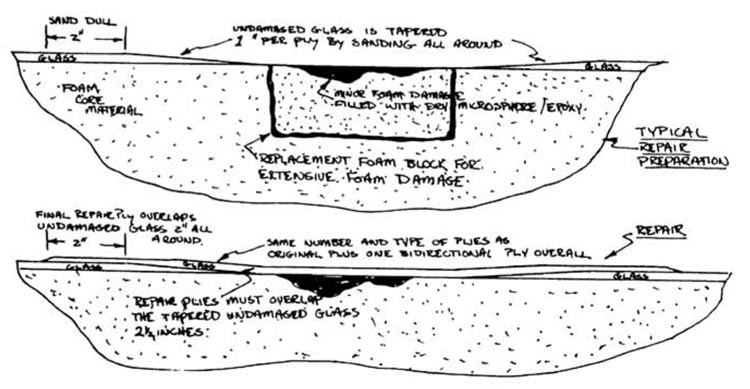
Voids greater than 2 inches in diameter should be repaired as shown in paragraph 4.
3.2 Lean Areas
Areas where the epoxy/glass matrix is incomplete because of inadequate wetting of the cloth with epoxy (lean areas) are speckled whitish in appearance. The fully wetted laminate will have a consistent transparent greenish appearance. Epoxy lean areas are acceptable, as long as the white speckled area is less than 10% of the surface area. White to green ratios greater than 10% require rejection or repair as shown in paragraph 4.
3.3 Rich Areas
Resin richness primarily adds weight to the laminate, While some degradation of physical properties does occur, overly wet (rich) layup is not grounds for rejection.
3.4 Inclusions
Bristle paint brushes are used throughout the layup process. As a brush begins to deteriorate it will shed some bristles into the laminate. The bristle inclusions, up to 20 bristles per square foot are not cause for rejection. Occasional inclusion of small woodchips or other small foreign objects is not grounds for rejection.
.
3.5 Fiber Disruption
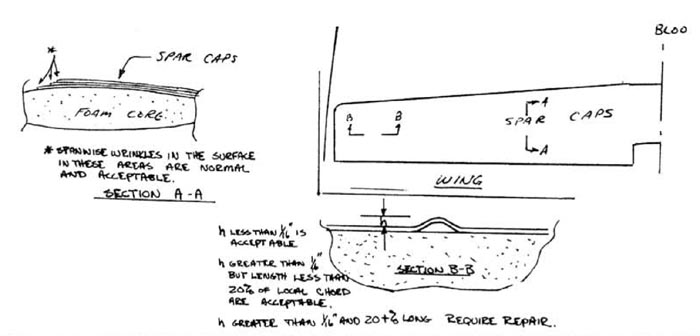
In all instances, it is good practice to have the glass fibers lying flat and without wrinkles, Major wrinkles or bumps along more than 2 inches of chord are cause for rejection in the wings, canard, and winglets, particularly on the upper surfaces (compression side). Disruptions greater than 2 inches require repairs per paragraph 4.
CONTINUED ON NEXT PAGE


