Q2 Plans Chapter 10 Page 10-08


- Details
- Category: Q-2/Q-200 Plans
- Published: Sunday, 21 May 2006 09:05
- Written by Quickie Aircraft Corporation
- Hits: 3413
|
.....
With the C517 hinge mounted on the elevator
up against the end of the QC5M2 pivot, and with the elevator in position in the elevator slot foam core, you can mark on the elevator slot foam core where the 2 C518 inserts must go. Next, route out the foam in the elevator slot foam core in preparation for later bonding of the C518 inserts in place. Any excess foam removed can be filled in later with flox during assembly.
.....Now, let's carefully review how the elevator is removed from the midspan elevator pivot. The elevator is moved inboard, resting on the QC5M3 stud, at least !" until it falls off the QC5M3 stud. During this movement, the C517 hinge remains where it was, since it was permanently attached to the canard (between a sandwich of C518 inserts) during assembly. .....Do you understand? Good, read the above explanation again two times until it is indelibly etched in your memory. .....Now you are ready to do the same thing for the right elevator. Remember that the QC5M2 pivot assembly, complete with QC5M3 stud, must be pushed into the C516 elevator torque tube with the stud pointing OUTBOARD. (A mirror image of what you have already done). Be very careful in setting up the right madspan elevator pivot assembly, and verify that it, too, will function as described in the paragraph above. .....It may seem that we are spending too much time on this setup, but it is the "voice of experience speaking". 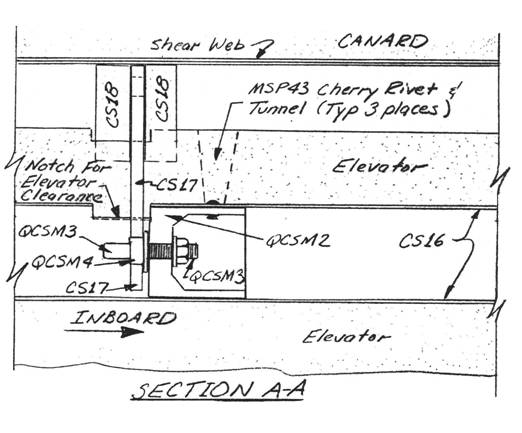 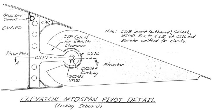 IN5TALLATION OF THE ELEVATORS
..... The elevators are installed and rigged prior to the canard being mated to the fuselage. As a result, after mating only C513 needs to be hooked up for a functioning pitch control system. .....The procedures detailed here are similar in scope to what you have already accomplished in mounting the ailerons on the main wing, except that the elevators have a center pivot on each side. .....Begin by jigging the canard vertically, with the leading edge at the table. .....Take a piece of QC5Ml and make two 1.8" 1ength pieces to use as elevator reducers. A sawcut and perhaps some light sanding will be necessary to make them fit snugly and flush with the inboard ends of the two elevators. .....Find the phenolic bearings C515 (2) and C514 (1). Dull the phenolic completely with sandpaper except inside the reamed 5/8" diameter holes. Be sure that the other 1/2" diameter hol es have been drill ed out. These are non-critical on diameter, but must be there to assist bonding of the phenolic to the structure. They are NOT lightening holes. .....Find Q2C5A8. Make C520 from 0.625" 0.0. x 0.065" wall 4130 steel tubin_. The length of C520 should be about 5" longer than 1/2 the width of the fuselage where the elevator matches up to the fuselage. The piece is made long initially, and then trimmed back as needed. .....The right and left elevators are nearly mirror images of one another. Each elevator has an outboard hinge C519, a midspan hinge C517, and a inboard hinge C515. Q2C5A8 slips into the elevator reducer at the elevator end, and over a AN271-B8 (or M52071-B8) universal joint near BLOO. On the right side, C520 slips into the elevator reducer at the elevator end, and through C514 and then over the same AN271-B8 (or M520271-B8) universal joint near BLOO. Clear, heh? .....The following procedure was developed to help you get the elevators mounted without binding, with the proper clearances, and with the ability to get them off again: |
||||
CONTINUED ON NEXT PAGE |
||||
PAGE
10-8 |
||||