Q-talk 90 - Cowl Flap - Everything Engines - VW

- Details
- Category: Q-Talk Articles
- Published: Wednesday, 23 December 2009 16:24
- Written by Dave Richardson
- Hits: 5927
If you have a Revmaster and you have high oil pressure, you might spell relief D-I-E?G-R-I-N-D-E-R.
Background
VW designed two different styles of crankcases incorporating either a single or dual oil relief valve arrangement. These relief valves are nothing more than a captive spring and a plug or plunger. The plunger normally covers an oil passage that goes back to the main oil sump. When the pressure is too high, the spring is compressed and an oil passage back to the sump is opened up. The higher the pressure, the more the plunger is pushed down and more oil is diverted out of the pressurized part of the oil system. The springs are calibrated to open at specific oil pressures so damage will not occur to the pressure sensitive areas of the engine.
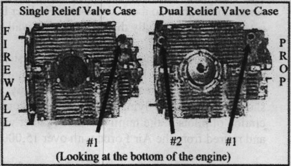
In both cases, when you look at the engine from the prop end, the primary oil relief valve is located in the forward lower left-hand corner of the crankcase. In a dual relief valve case, there is another similar hole in the aft lower left-hand corner of the main sump. You may have to remove the oil cooler or use a mirror to view the aft relief valve. Revmaster engines with an oil filter arrangement include a pressure relief valve in the oil pump case.
In Revmaster engines with an oil filter and oil cooler, the oil travels from the oil pump, located in the center of the engine below the prop, to the oil filter. From there it moves to the oil cooler installed under the engine. The filtered and cooled oil is routed up through the front oil relief valve hole in the case for distribution throughout the engine.
Dual Relief Valve Cases
If your case has a dual relief valve arrangement, there are actually two relief valves. One is in the case and the other is in the oil pump cover. If you have oil pressure problems, you should first remove the oil relief valve in the aft lower left-hand corner of the main sump to see if it is jammed or in some way unable to function properly. The modifications to the oil pump cover shown below may be of some benefit, if you still have oil pressure problems after checking the one in the case.
Single Relief Valve Cases
If you have a single relief valve case, the only oil relief valve in the entire system is the one on the oil pump cover. For high oil pressure problems, you need to examine this relief valve.
Over the years, Revmaster used two different plunger designs in the relief valve located in the oil pump cover. The first design incorporated a stainless steel ball about 3/8" in diameter as the plunger. The more recent design has a cyl-inder-shaped plunger. While the cylinder-shaped plunger is the preferred design, most of the engines sold with Q2 kits probably have the older ball arrangement.
Revmaster also learned that the oil passages from the oil cover relief valve back to the crankcase were restricted and less than optimal for very high-pressure situations. They made a change to the castings used for their oil pump covers to better mesh the relief side of the oil pump cover and the low pressure side of the oil pump. Again, in dual relief valve cases, this restriction may not play a big part because the relief valve inside the case can handle the job. If that second relief valve is jammed, however, these restrictions may become an issue.
I had very high oil pressure on my Revmaster with a single relief valve case. High enough to burst an oil filter in about 40 seconds of running. I contacted Allen at Revmaster and found out there was a very simple procedure you could do to tell just how well your passages are setup between your oil pump and oil pump cover. First, remove the exhaust pipe for #4 cylinder to gain better access to the area. Then disconnect the large AN fitting that feeds oil into the rear of the oil cooler. Remove the four bolts holding down the oil pump cover. The pump cover will be held in place by two rolled spring steel pins. These pins are designed to remain in the pump cover but pull out of the oil pump housing. You will have to wiggle the cover until it comes off. DO NOT use a screwdriver or other implement to pry the cover off. This will only scratch the inside surface and possibly lead to an oil leak later. The key is to try and pull the cover straight off instead of at an angle. You are going to fight with it, but it will come off eventually. Avoid damaging the very thin o-ring gasket that is between the oil pump and the oil pump cover. DO NOT attempt to remove the oil pump housing from the crankcase once you remove the oil pump cover.
Clean the oil off the inside face of the oil pump cover with a clean rag. Remove the o-ring from the oil pump housing and place it in a clean area. Remove the lower and upper pump gears from the oil pump housing. Place the gears in a clean area. Remove any oil in the oil pump housing with a clean rag.
Place a 4" x 4" clear plastic rigid film, like used on an overhead projector or something similar, over the oil pump housing so it is entirely covered, including the bolt holes. Outline the recessed oil pump housing areas where the gears were located with a Sharpie pen. Be sure to mark the locations of the four bolt holes and the spring steel pin holes. Label the right side of the clear plastic with RT so you later identify the front and back sides of the plastic.
To allow you to place the clear plastic flush against the inside surface of the oil pump cover, use a hole punch, or something similar, to remove the area around the pin holes. Don't worry about being ultra precise with the punched holes because you will be using the bolt holes to line up the plastic on the oil pump cover. Let the ink dry for a few minutes. Place the marked side of the plastic against the inside surface of the oil pump cover. You can now draw on the back side of the plastic to outline the two oblong oil pump cover passages. When completed, you will see clearly what the oil has to go through to gain access to the main oil sump and come out of the pump. On mine, the outgoing high-pressure oil passages meshed fairly well and did not require any changes. There was a problem, however, on the low-pressue side of the pump where the relief valve dumps its oil back into the sump. The relief side oblong trough in the oil pump cover was only meshing with about an area of 3/8" x 3/8". The low-pressure side had a much larger area for depositing oil than was being utilized.
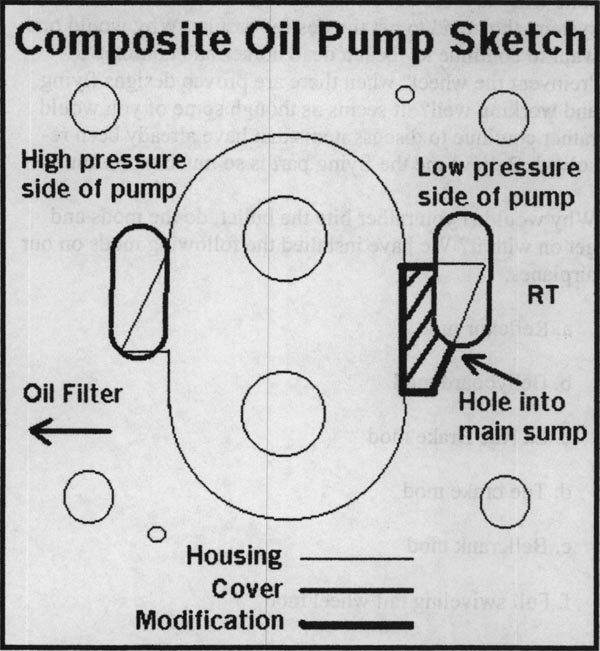
I marked the inside surface of the oil pump cover using a Sharpie pen with a line similar to the thick line shown in the drawing. I plugged all the holes in the oil pump cover with bits of paper towel and covered the inside surface with duct tape to help reduce scratches. I used a die grinder, or I could have used a small rotary file, to remove the material from the relief valve trough out to my guidelines. I tried to go as deep into the material as the existing trough.
While I had the pump open, I checked to be sure the hole on the inside wall of the high-pressure side of the oil pump housing was plugged. There were old reports in Q-Talk that if that hole was open it prevented the oil from going to the oil filer and oil cooler and resulted in high oil temperatures. I also checked for a large opening on the inside wall of the low-pressure side of the pump. This hole allows oil to be drawn into the pump from the main oil sump and diverted back to the oil sump in a high-pressure situation. The hole on the right inside surface MUST be OPEN.
After I removed the duct tape and paper towel, I cleaned off the grindings from the oil pump cover and was ready to reassemble the oil pump. I replaced the o-ring gasket in the circular grove without any adhesive. I replaced the top drive gear in the pump and made sure that the flat drive portion of the shaft was engaged with the drive mechanism behind the oil pump. I placed a large glob of STP oil treatment on the lower gear and meshed the two gears together. The STP would ensure a good charge in the oil pump when I would run the engine the first time. I made sure that both of the gears were flush with the front of the oil pump housing and that the lower gear shaft was seated back into the housing. Per instructions, I did not use RTV or any other adhesive when I bolted the cover back on the oil pump. Just make sure the thin o-ring is seated properly to act as a seal. I reattached the AN fitting that feeds the rear of the oil cooler from the oil filter.
When running the engine, it is normal for the oil pressure to be higher at first until the oil is heated. Oil pressure of 50 to 80 psi is not unheard of during the first few minutes. At temperature, the oil pressure should drop to approximately 10 psi for every 1000 rpm according to Revmaster. You can adjust the oil pressure by tightening and loosening the adjuster screw found on the right side of the oil pump cover. You increase the oil pressure by rotating the adjuster screw clockwise and reduce the pressure by rotating counterclockwise.
This is a simple modification to your oil system that can be done in an evening. Hopefully, this will be a solution to your high oil pressure problems or just help you better understand the Revmaster oil system. When I ran my engine after making this modification, the oil pressure went from 90+ psi to about the 50-55 psi range during the first minute of running. I was pleased with the results. While I have not flown this solution yet, it does appear to be promising. By the way, Revmaster was willing to make the change, too.
You can order a printed copy of Q-talk #90 by using the Q-talk Back Issue Order Page.