Q2 Plans Chapter 9 Page 9-06


- Details
- Category: Q-2/Q-200 Plans
- Published: Monday, 22 May 2006 09:05
- Written by Quickie Aircraft Corporation
- Hits: 4271
|
OUTBOARD AILERON PIVOT ASSEMBLY
..... These instructions cover only the assembly of the left outboard aileron pivot, but the right outboard aileron pivot is a mirror image, and may be accomplished at the same time. .....First, find a QCSM7 pivot and position it about 0.25" inboard of the outboard end of the aileron using 3 MSP43 cherry rivets spaced radially at least 0.4" apart. .....Find CS10, and insert a QCSM5 stud as shown with the 3 washers and the 2 AN363-428 nuts. There must be a minimum of 0.6" from the AN960-4 washer inboard to the end of the QCSM5 stud. This is to require the aileron to be moved inboard at least 1/4" before it II fa II s off" the QCSM5 stud for dissassembly. Finally, round the end of the QCSM5 stud slightly to assist in mounting the aileron. .....The sketch shows the outboard aileron pivot assembly as it will look later when installed on the main wing shear web. Although not shown, at that time, the aileron slot foam core and aileron trailing edge foam core will be trimmed so that CS10 will fit flush against the main wing shear web. 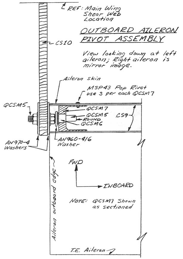 AILERON INSTALLATION
..... In this section, you will mount the ailerons to the main wing. After the main wing is attached to the fuselage, it will only be necessary to connect the CS5 and CS12 push-pull tubes in order to have a functioning aileron control system. This section is very important, so take your time and read through the entire section several times prior to starting any of the procedures. .....Begin by jigging the main wing vertically on your jig table with the L.E. pointed down. This will make it much easier to rig the ailerons. 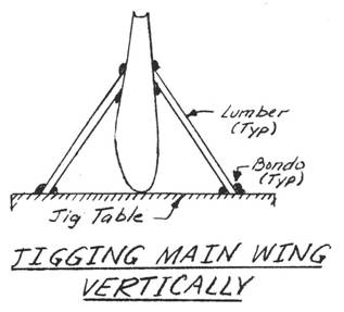 ..... Take a piece of QCSM1 and make two 1.8" length. pieces to use as aileron reducers. A sawcut and perhaps some light sanding will be necessary to make them fit snugly and flush with the inboard ends of the two ailerons. .....Find the phenolic bearings CS6 (2) and CS7 (2). Dull the phenolic completely with sandpaper except inside the reamed 5/8" diameter holes. Be sure that the other 1/2" diameter holes have been drilled out. These are non-critical on diameter, but must be there to assist bonding of the phenolic to the structure. They are NOT lightening holes. .....Find Q2CSA4 (2). Make CSll (2) from 0.625" O.D. X 0.065" wall 4130 steel tubing. The length of CS11, which can be critical for disassembly, should be about 3/4" less than half the width of the fuselage at the aileron torque tube (CS9)/ fuselage junction. .....The right and left aileron mountings are mirror images of one another. Each aileron has an outboard hinge (CS10), an inboard hinge (CS6), and a center fuselage hinge (CS7). The Q2CSA4 slips over a CS11, which passes through the CS6 phenolic and slips into the aileron reducer, which is mounted on the inboard end of the aileron. Clear, heh? |
||||
|
||||
PAGE
9-6 |
||||