Q2 Plans Chapter 4 Page 4-02


- Details
- Category: Q-2/Q-200 Plans
- Published: Saturday, 27 May 2006 12:05
- Written by Quickie Aircraft Corporation
- Hits: 5142
|
..... It is important to note that if you modify either your Seatback Bulkhead angle (see Chapter B) or Instrument panel location, or if you are wider and bigger than normal in the hips, you may wish to change the geometry of the pieces somewhat. If that is the case, wait until later to make these pieces. INSTRUMENT PANEL
..... The template provided for the instrument panel on Appendix Sheet 3 is intended to be used with the 1/8" thick aircraft quality plywood provided with the kit. It is suggested that the panel not be mounted in the fuselage permanently until cutouts for all instrument panel gauges, radios, and equipment have been made. It will at times be useful to install the panel temporarily with Bondo to assist in jigging parts of the fuselage. PLYWOOD PARTS
..... In this section, you will construct the following pieces: firewall, LG4, CSI0, CSI9, CS22, BS2, and BS3. All parts are constructed from 1/411 Marine grade plywood. See Appendix Sheet 3 for the full size template drawings, which can be pasted on the plywood itself. As indicated previously, the writing on the template drawings can be read when the part is right side up. Also, the drawings indicate the number of each piece to be made. ALUMINUM PARTS ..... On Appendix Sheet 2, you will find the full size template for the 0.125" thick 2024T3 Aluminum supplied. Other parts, not detailed here will be made at a later time from aluminum. PHENOLIC BEARING BLOCK
..... On Appendix Sheet 2, you will also find the full size template for the predrilled Phenolic bearing. block Q2CSP. Refer to the "Introduction" of this chapter for information. FEMALE JIGGING TEMPLATES ..... These full-size templates provide the basis for jigging the vertical fin, fuselage, main wing, and canard. They are found on Appendix Sheets 2, 4, and 5. Make 2 of each, except make 1 of each of the vertical fin jigging templates. RIGGING TEMPLATES ..... Rigging templates allow the builder to accurately rig the ailerons, elevator, and rudder for proper travel. These full-size templates may be found on Appendix Sheets 1 and 5; make 1 of each. WHEEL PANT PIECES ..... On Appendix Sheets 1 and 3 you will find fullsize templates for the pieces that comprise the wheel pants, including the templates to assist in carving the shape. Thickness of LG1, the wheel pant cores, is 6.7 inches each. The 4 LG21s are made from the /" thick white foam. The 3 carving templates are made from hardboard, plywocd, masonite, etc. FUSELAGE BULKHEADS ..... In this section, you will construct the following bulkheads: FS120, FS94, Seatback Bulkhead, and aft canopy bulkhead. All bulkheads are made from the 3/B" thick white foam. You will find full size template outlines on the large Appendix Sheets 1 and 2. On this sheet, you will find sketches showing the foam layouts. Where two full size template outlines are overlaid with one another, work your way in toward the middle by making the outside template bulkhead first, then trimming the template down so that the inside bulkhead can be made. (e.g. make FS94 bulkhead first, then make the FS120 bulkhead). 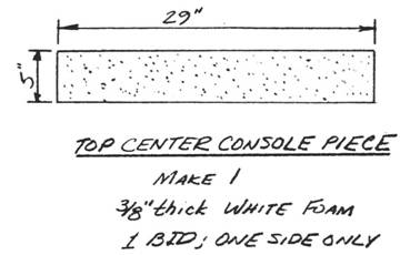 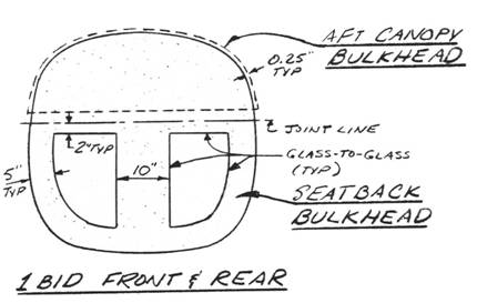 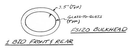 ..... Each full size template outline has a forward face marked on it. Also, the words describing the template are always written so that they can be read when the template is right side up and facing forward. Be sure to mark each bulkhead upon completion with the proper information so that you don't forget which way it is jigged. Each bulkhead will jig into the fuselage only one correct way. .....The Seatback Bulkhead is made in two pieces and joined together upon assembly of the fuselage. On Appendix Sheet 2, you will find the full size templates for both the canted piece (i.e. lower piece) and the vertical piece (i.e. upper piece). In order to conserve space, the templates are laid out with the joint between the two pieces as the common line at the top of the template. This is the only case in these template drawings where the presentation is not consistant. Note also that the template drawing for the vertical piece calls it out as being used for the aft canopy bulkhead. To make the aft canopy bulkhead, use the vertical piece of the Seatback Bulkhead and reduce its height to 15 inches by cutting off the bottom of the template. Also, since the canopy is much thinner than the fuselage core, make the vertical piece template curve "fuller" by approximately 0.25 inches. The result will be that when compared to the vertical piece of the Seatback Bulkhead, the aft canopy bulkhead will be not as tall, but will have a larger radius of curvature by about 0.25 inches. |
||||
END OF CHAPTER |
||||
PAGE
4-2 |
||||