CANARD SURFACE SMOOTHNESS IS CRITICAL
.....During
the Quickie program we built and installed a canard that resulted in
very poor low-speed performance. Stall speed was 10 mph higher than
predicted and tuft tests showed stall angle-of-attack over three degrees
lower than estimated. We later traced the problem to a wavy upper surface;
the canard must be
smooth.
.....Of course, the big question is "how smooth"? The best way to check
this is with a steel pocket ruler, the flexible kind that's only .0211 thick,
or with
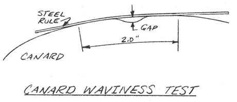
a plastic drafting ruler. Hold the ruler as shown in the sketch, pushing it to
the surface with two fingers 2 inches apart. If the surface is a smooth curve
between your two fingers the ruler will lay down following the curve with no
gaps. If the surface is bumpy or wavy the ruler will touch the surface only in
3 or 4 places. Take a feeler gauge
to measure the gaps between the ruler and your surface. If you have a gap of
more than .005 inch, your surface is too wavy. Check this in several places from
the leading edge back to 50% chord. The bad Quickie wing had gaps of about .012
inch. After refinishing with gaps of less than .005 inch, its stall angle of
attack increased from 8 deg. to 12 deg!
.....The best time to use the ruler and check
for smooth surface is when sanding the Featherfill with the spline. Recheck after
sanding the 70S black primer. It will not change when white paint is sprayed
on.


AMATEUR-BUILT Q2 INSPECTION CRITERIA
1.0 SCOPE
.....
This document has been prepared to assist inspection personnel by providing recommended acceptance criteria and acceptable repair practices for the Q2 amateur-built composite sandwich structure.
2.0 BACKGROUND INFORMATION
2.1 DESIGN CRITERIA
.....
The materials, methods, and practices employed
by the amateur builder in the construction of
the Q2 type are new to light aircraft construct¬ion and may be unfamiliar to the inspection personnel involved with the licensing of amateur¬built aircraft. Structural design criteria
for the Q2 exceed F.A.R. part 23 requirements.
In-house component testing of the primary flight structure has been conducted to 200% of design limits. Detail documentation of test data is
on file at Quickie Aircraft Corporation. The aircraft is considered to be a utility category aircraft. Q2 builders are being supplied with
a complete owner's manual which specifies all placards, operating limitations, normal and emergency operations, flying qualities, maintenance SP' cifications, inspection proced¬ures, and initial flight test procedures.
2.2 STRUCTURAL APPROACH
.....
The basic structure throughout the design is a composite sandwich of load bearing fiberglass skins separated by a light-weight foam core.
While the materials and processes are tailored to the amateur builder, the structural layout
is very similar to the honeycomb composite structures stilized in military and transport
type aircraft and fiberglass sailplanes.
Loads are carri ed by epoxy j"EIl-type fi bergl ass lamina. Foams of various types and densities are employed as a form (upon which the load bearing material is shaped) and as local buck¬ling support. In no instance are foams used
to transmit primary loads, as is the case in
some other amateur-built designs.
2.3 INSPECTION TECHNIQUES
.....
The transparent nature of the fiberglass/epoxy material allows for visual inspection of
primary structure from the outside prior to finishing. Defects in the structure, as
described in paragraph 3.0, are readily visible even in the deepest laminate.
2.4 INSPECTION SEQUENCING
.....
The external visual inspection capability pro¬vided by the materials allow inspection of all primary structures at any point before finish¬ing. All primary structures are at the surface, eliminating the requirement for IIpre-coverll
or IIclosurell inspecti ons. Opaque fi 11 er
materials are used throughout the airplane in finishing, and inspection must take place
before any areas are obscured. Some areas may have opaque materials applied to one surface
where the structure is inspectable from the opposite side (wing trailing edge for' example).
3.0 DEFECTS
3.1 VOIDS
.....
Interlaminar voids in a new layup may be due to small air bubbles trapped between plies during the layup. These void areas look white and are distinctly visible even deep in a cured layup. Interlaminary voids up to 1 inch in diameter do not require repair, as long as they do not consist of more than 5% of the surface area.
Interlaminar voids (airbubbles) up to 2 inches in diameter are acceptable when repaired as follows: A small hole is drilled into the void and epoxy is injected into the void area. Small voids such as this may occupy up to 5% of the laminate surface area.
Voids greater than 2 inches in diameter should be repaired as shown in paragraph 4.
CONTINUED ON NEXT PAGE
|


