ELEVATOR MASS BALANCING
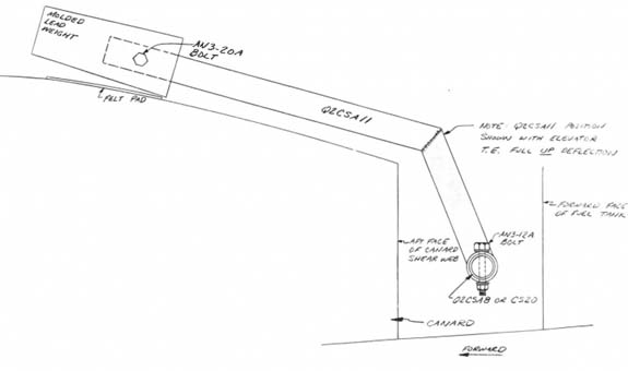
.....Locate the two Q2CSA11 arms and the molded lead weights.
.....These elevator mass balance arms can be retrofitted to the elevator control system even after the canard has been mounted to the fuselage. This will allow a closer clearance with the fuselage sides and maximize the available legroom. If the mass balance arms are installed prior to mounting the canard, careful measurements must be made to assure clearance with the fuselage sides.
.....Begin by attaching a molded lead weight to each Q2CSA11 as shown.
.....Next, remove the two bolts holding CS20 in position, and slide it outboard through the CS14 phenolic bearing until a Q2CSA11 arm can be slid onto the tube with the lead weight projecting forward. Reinstall the bolts holding CS20 in position.
.....Then remove the three bolts securing Q2CSA8 and slip it inboard until the second Q2CSA11 arm can be slid on the outboard end inward with the lead weight projecting forward. Reinstall the bolts holding Q2CSA8 in place.
.....Locate the Elevator Rigging template and jig the elevator in the full trailing edge up position. With the elevator in this position, each Q2CSA11 should be almost resting on the canard upper surface just inboard of the fuselage. Note the piece of felt called out as a bumper stop. The Q2CSA11's are located as far outboard as practical so as not to interfere with pilot or passenger legroom. Verify that when the elevator is rotated to full trailing edge down position, that the arc of each Q2CSA11 clears the fuselage and all other components.
.....Finally, return the elevator to the full trailing edge up position with each Q2CSA11 resting almost on the canard, and drill in the one AN3-12A bolt per side to attach the Q2CSA11's to Q2CSA8 and CS20.
.....Leave the CS13 pitch control arm unattached from Q2CSA8, and remove the two AN4-11A bolts attaching the universal joint to Q2CSA8 and CS20. Remove the universal joint so that each elevator can rotate independently of the other. Make sure that you have lubricated all of the bearing
and hinge points to reduce the system friction to a minimum. It is desirable for each elevator to balance at 0 degrees to 2 degrees trailing edge up with all painting and finishing complete. Remove lead, as necessary from the molded lead weight until that postion is reached. Each elevator should rotate freely about the hinge points when given a slight nudge. Failure of this check means that the pivots are too tight and must be adjusted for minimum friction.
.....Once the amount of lead weight on each elevator has been adjusted, bolt the entire pitch control system together and check for friction, excess play, and interferences.


