Q2 Plans Appendix Page ii

- Details
- Category: Q-2/Q-200 Plans
- Published: Wednesday, 31 May 2006 12:05
- Written by Quickie Aircraft Corporation
- Hits: 8134
Q2 PLANS ADDENDUM | ||||
Q2 Builder Tip Notices (Q2BT9) are intended to provide clarification, guidance, improved construction methods, and helpful hints of a non¬mandatory nature. The builder, at his descretion may use or discard any Q2BT. Most are a result of work accomplished at Quickie Aircraft Corporation building a Q2 from the Q2 Construciton Plans. Any questions on a Q2BT notice should be referred to Quickie Aircraft Corporation. Each Q2BT has a number and a publication date along with a description of the builder tip. | ||||
NUMBER | DATE | DESCRIPTION | ||
Q2BT9 | 1 July, 1981 | Q2 CONSTRUCTION PLANS - SECTION I: Some plan sets sent out may have faint re-production on parts of pages 9-8, 10-1, 10-2, 10-3, 11-4, 14-2, and Appendix Sheet 4. We intend to have those sections reprinted within 30 days. We will send the reprinted sheets to any builder who reports this problem. | ||
| Q2 Plans Change Notices (Q2PC9 & Q2PC10) are mandatory revisions to the Q2 plans. Each Q2PC has a number and a publication date along with a description of the change. All Q2PC notices should be incorporated into the builder's set of Q2 Construction Plans immediately upon receipt by the builder. Any questions on a Q2PC notice should be referred to Quickie Aircraft Corp. | ||||
NUMBER | DATE | DESCRIPTION | ||
Q2PC9 | 1 July, 1981 | Q2 GROUND ANGLE OF ATTACK: With the aircraft assembled and WL15 level, and with the aircraft on a reasonable level floor, take a measurement vertically between the floor and the bottom of the tailwheel. The nominal measurement should be 27". A range from 25" to 28.6" should be Acceptable. This limitation is to assist tailwheel first landings and three point takeoffs at mid/forward c.g. Small change can be effected by changing the tailwheel diameter. It is a good idea to delay mounting the tailspring until the aircraft is assembled, so that the proper height can be achieved. | ||
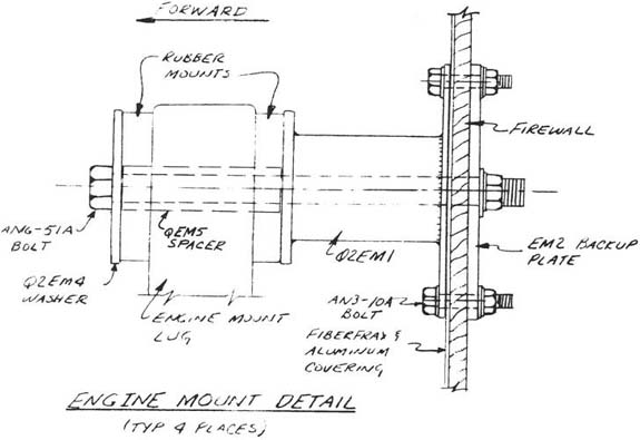
Q2PC10 | 1 July, 1981 | ENGINE MOUNT INSTALLATION, P-16-2 does not indicate the required spacer. The material is 4130 steel, or mild steel of 1/2" 0.0. x 3/8" 1.0. The sketch indicates the location of this QEM5 spacer (4 required). | ||
 | ||||
ii | ||||