LS(1) 0417 MOD CANARD INSTRUCTIONS


- Details
- Category: Q-2/Q-200 Plans
- Published: Tuesday, 30 December 2014 02:44
- Written by Sam Hoskins and Dan Yager
- Hits: 40501
LEGAL DISCLAIMER: This document is provided as an incomplete record of events to inform those who may desire to construct similar parts. This information is not intended to serve as design advice. The author does not warrant that it is complete, comprehensive or accurate, or commit to its being updated. You agree that making this information available shall not be seen as the provision of design advice, and therefore I, my heirs, employer, and/or any other agent acting on my behalf are not liable in any way for its use or for the consequences of any actions taken on the basis of the information provided
[EDITOR’S NOTE: The text below is an attempt to improve the instructions for building an LS1 Mod Airfoil Canard for the Q-200 aircraft. The text and photos below are a combination of the original text and photos from LS(1) 0417 MOD CANARD construction documents provided by Quickie Aircraft Corporation. I have also included text and drawings from the Q2 and Quickie Plans when referenced, as well as construction notes provided by a builder as he reconstructed his canard after an accident. The text and images are provided for informational purposes only. Please read and understand the LEGAL DISCLAIMER above before attempting to use this information in your own design.]
CONSTRUCTION OF LS(1) 0417 MOD CANARD
The canard construction consists of seven basic parts.
· Hotwire all foam cores.
· Build the elevators.
· Join the two carbon fiber spars.
· Attach foam cores to the spars.
· Glass the upper and lower surfaces of the canard.
· Attach and glass the elevator slot cores.
· Install the elevator attach brackets.
· Build and attach the wheel pants and brakes.
BUILDER’S TIP:
Use BLUE Dow Styrofoam or equivalent. The older style orange foam seems to have internal stresses, which can result in warped parts, particularly thinner components such as ailerons and elevators. Also, much of the original kit foam is now 30+ years old.
BUILDER’S TIP :
At the time of this revision, precut cores are availablevia EUREKA CNC – Steve James has a vendor account here on the Quickie Builders Association website and you can buy his foam cores directly. Seriously consider using this high quality source since it will save you many hours of sourcing foam , dealing with templates, alignment, making mistakes, etc.
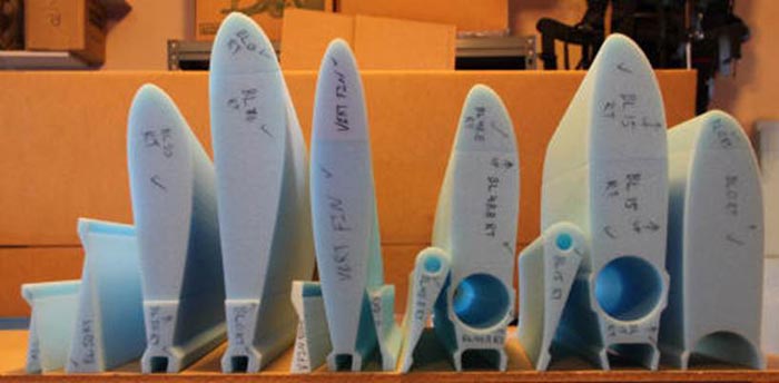
CNC Foam Cores from Eureka CNC
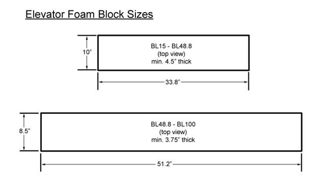
From BL15 to BL100, the hotwire block sizes are exactly the same as called out in the Q2 Construction Plans. . .
Q-2 Plans: Page 5-2
CANARD CORES
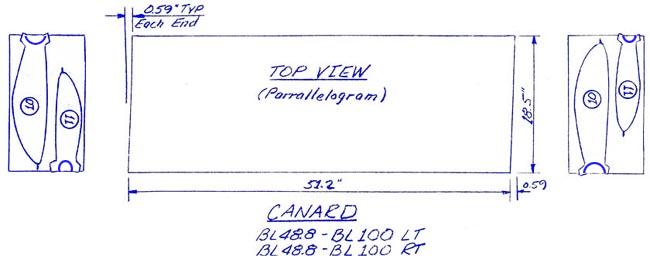
The outboard and inboard canard cores are cut from skewed, parallelogram style blocks, with the exception of the canard center section. The reason for this is to obtain the proper sweep of the canard when the cores are jigged together later.
Begin by squaring up the 10" x 20" X 96" nominal dimension block of polystyrene foam to obtain a length of 51.2", with the skew as indicated. Next, using the sketch provided, hot-wire the outboard canard foam cores. Note that the bottom set of templates are upside down, so as to obtain the proper geometry upon jigging.
Next, find the extra pieces from the 10" x 24" blocks (2) and face them up to the dimensions shown. These two blocks are used for the inboard elevator cores and inboard canard cores. The portions not used will be used later for the outboard elevator cores.
Q-2 Plans: Page 5-3
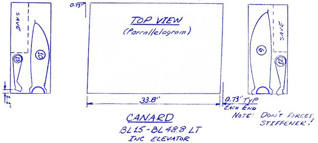
Locate the remaining part of the 10" x 20" block and size it as shown, in order to make the canard center section. Keep the unused portion for cutting the vertical fin, so don’t make the height over 6.0". Note the 0.6" taper dimension is to allow for the proper anhedral angle upon assembly in the canard female jigging templates.
. . . From BL0 to BL15, we use two pieces instead of the one used in the old GU canard. 1. The blocks for these should be sized to 15.70" long. These sections are jigged after the spars and other hotwired sections have been located. A bevel will need to be sanded to allow for the canard's anhedral. Trial fit cores in place, check transition alignment, and sweep aft. From BL15 to BL100, you should measure about 10.5" at L.E. foam cores.
IMAGE FROM PLANS REPLACED WITH SKETCH BELOW
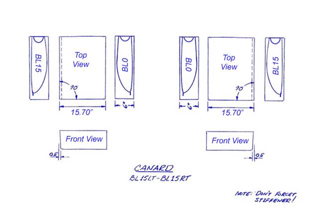
NOTE: Cut one LEFT and one RIGHT center core using the BL0 and BL15 templates.
BUILDERS TIP:
The following sentence appeared at this point in the original LS1 Construction instructions:
You may want to skip ahead and build the elevators now. At any rate, they must be built before you attach the elevator slot cores.
Since it is advisable to construct the elevators first, we have re-arranged the original instructions to include elevator construction prior to the construction of the canard.
OUTBOARD ELEVATOR CORES
Hot wire for the elevator torque tubes like you did on the inboard elevator cores.
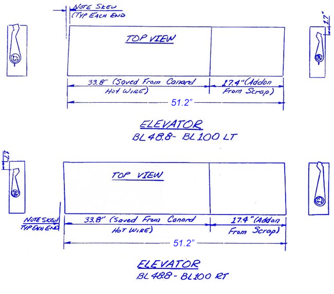
BUILDER’S TIP:
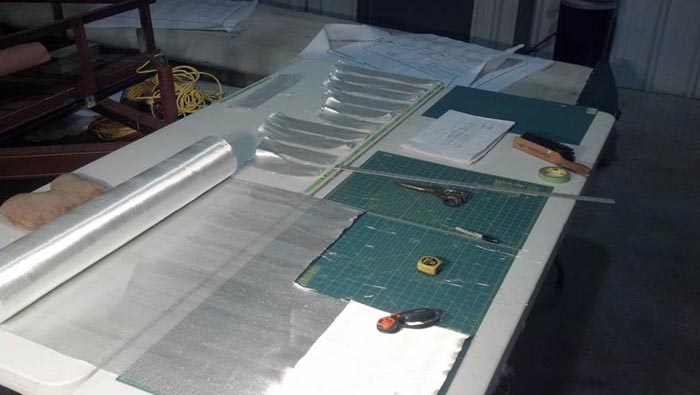
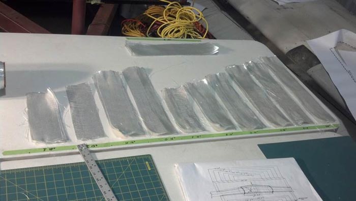
In order to avoid the hassle of putting scrap pieces of foam together, you may want to purchase additional foam, so you can cut everything out and have just two pieces . (As shown below.)
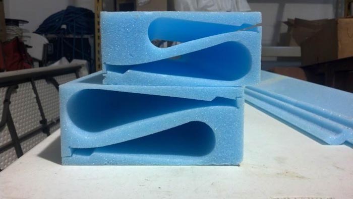
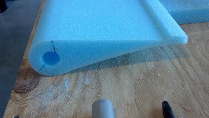
Shown above are the foam blocks after cutting out the elevators.
Note that you cut LEFT and RIGHT elevators out of the same block
by flipping the templates over and placing them on the opposite ends.
Note that the templates only show 1 slot for cutting the hole for the torque tube.
BUILDERS TIP:
The Q-200 elevator templates only show one cut for the torque tube. It is suggested you make two cuts as shown below. Otherwise , it is all but impossible to adequately bond the cores to CS16 without voids .
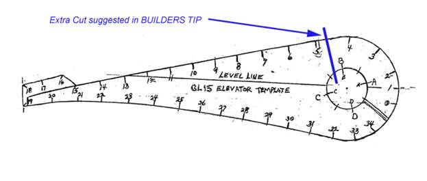
NOTE: Above drawing not to scale.
Suggested extra cut marked with a felt tipped marker.
BEFORE BUILDING THE ELEVATORS:
Find CS16 (72” Aluminum Tube), QCSM7 pivot and QCSM6 bushing. Push QCSM6 into QCSM7 until seated. Push QCSM7 into CS16. Use 3 MSP-43 cherry rivets spaced radially at least 0.4" apart, to secure in place. This will become the outboard pivot for the elevator. Note: the original plans had you do this after building the elevator, doing it now will prevent the need to drill the rivet holes through the complete elevator.
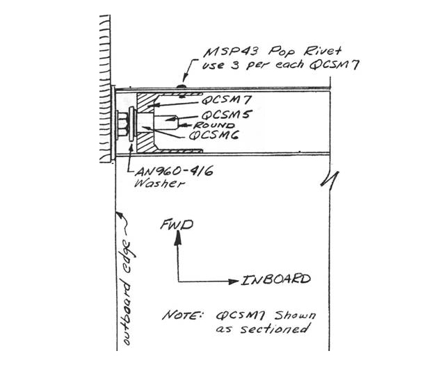
Detail of Drawing from QAC Q-2 Plans p 9-6
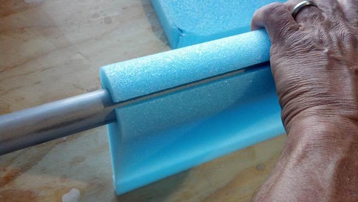
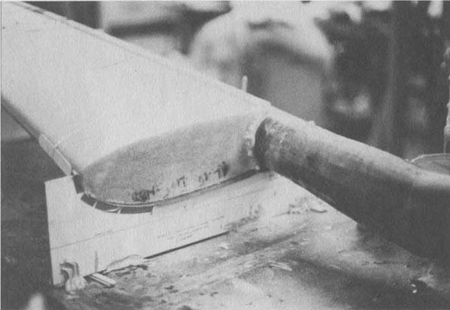
Use some ingenuity and fashion tools to enlarge the hole for the torque tube to fit a little better, and making a little room for the micro. You can fashion tools out of the spare foam or use a wooden dowel. Do not get too aggressive sanding in this area.
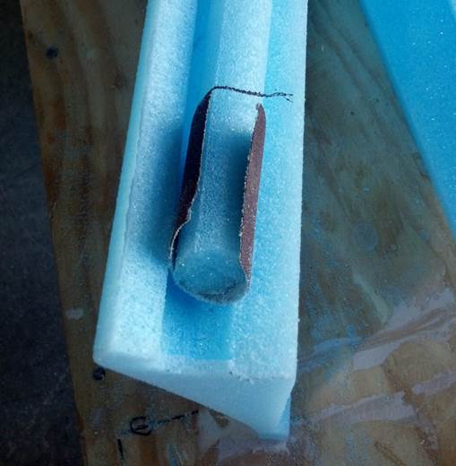
Then “Check Fit” until you are happy with the result. In the photo below, more sanding of the center hole is required to close that gap.
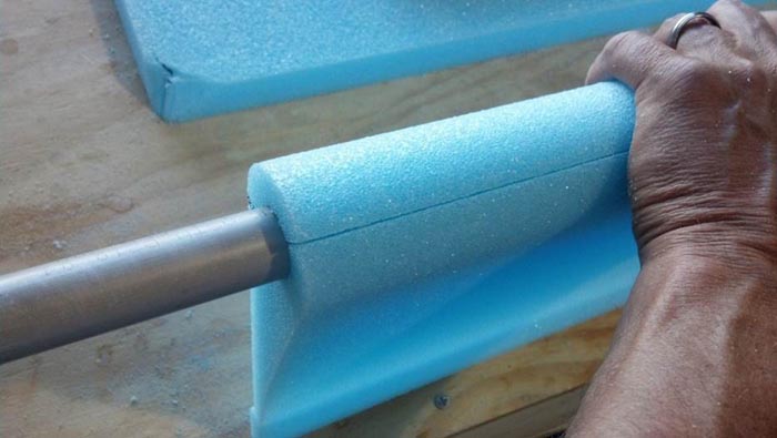
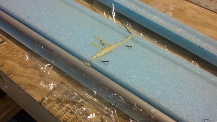
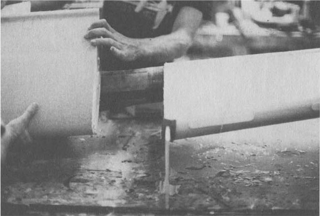
Join the cores together with expandable foam and temporarily maintain alignment using your torque tubes.
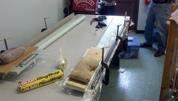
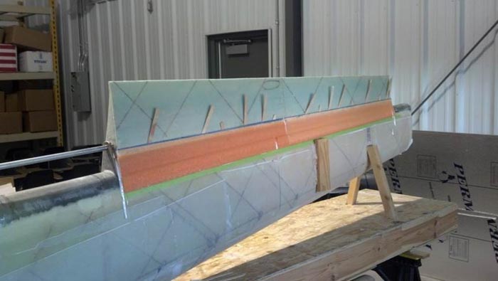
This photo shows the use of saran wrap to keep the expanding foam from attaching to the torque tube while jigging the cores. Naturally you will remove this plastic wr a p prior to glassing the cores.
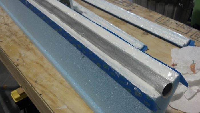
You will now have an elevator core that is too long and the outboard section must be trimmed. Measure 72” from the inboard end of the elevator foam core. T rim the outboard portion so the core is now 72” long. Now it ’s time to permenantly install the torque tubes into the cores , but f irst, p repare your elevator jig templates and hot glue them in place on your work table.
The liberal use of painter ’ s tape helps applied to the torque tube will keep the micro from spreading and prevent you from having to dress it up after the micro has cured. We also apply painters tape to the foam, as shown below, to help keep things clean and tidy. Once you have the torque tubes embedded in the cores, you may remove the tape so it doesn’t become a permanent fixture of your elevator. Like the canard, wrap with rubber bands. Set the assembly into the jigs for curing. Double-check to ensure the cores are perfectly straight and not sagging. You can wedge scrap foam under the elevator to help hold the alignment.
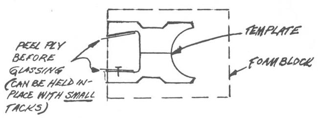
Apply peel ply to bare foam trailing edge 1/4" to 3/8" before glassing for a stippled close-out.
Use the templates provided in the plans to construct the elevator jigs, and ensure proper alignment of all parts before continuing.
Glass your elevators with 2 UNI at ±45° to the trailing edge, just like the aileron. Measure the elevator foam cores and then cut the UNI cloth to the proper size. More than one piece of UNI will be required to cover the entire 72" elevator span. Where the UNI pieces join, no overlap is needed, (i.e. butt joint is OK) but stagger the joints on Ply #2 so that the foam along the butt joint line is covered. Lay up these plies exactly like you did on the ailerons. Don't forget the foam scraps in the end of CSI6. Do not trim the trailing edge until after the elevators are mounted on the canard.
After the layup has thoroughly cured, you may break it loose from the jig and flip it over. You will not use a jig for the top side of the elevator.
When you sand down the tabs for glassing the top surfaces, note that the elevator has a blunt trailing edge . That is normal . Refer to the hotwire templates. After glassing the top side, sand the elevator trailing edges to length. Then remove some foam (1/4") and fill with dry micro to prevent the skins from peeling. Coat with pure epoxy first.
BUILDER’S TIP :
After you glass the second side, find an extremely flat table and lightly clamp and/or weight the elevator to ensure that it cures flat.
CANARD CONSTRUCTION
JIGGING THE CANARD
Next, you will need to jig the canard cores on the jig table. It would probably be a good idea to clean off the jig table of any bondo chips, wood, epoxy, etc., so that you start with a clean surface.
Find the canard core female jigging templates (6)
Now study the sketches. The canard cores are jigged upside down on the jigging table using the canard core female jigging templates. If your table is not at least 200 inches long, you will have to extend it like you did on jigging the main wing.
Begin by drawing a straight line along your jigging table and marking the locations (BL's) of the canard core female jigging templates. Next, temporarily set the canard core female jigging templates on the jigging table so that their leading edges are the distances from the straight line, called out in the accompanying illustrations.
Now begin to trial fit the four outboard canard cores into position. Be careful in handling the foam cores to prevent damage to the foam. All cores may have to be sanded in order to make them fit together within the maximum tolerance of 1/16".
Establish a BL15 reference line on the topside of your canard jigging table. This can be done with a long straight edge or chalk line. Locate and mark on your table BL0-0, 15, 48.8, and 100, both sides. Place the leading edge of the jig blocks BL15, 48.8, and 100 in their respective places (they are glued to 1/4" or thinner plywood, fiberboard, etc.).
BUILDER’S TIP:
Use a Hot Glue Gun for temporary fastening of spars. You can also use the Hot Glue Gun to fasten template jigs to the work surface, or any place else in these instructions that call for 5-minute epoxy or bondo to temporarily tack anything in place. Make sure you remove all traces of hot glue when making structural parts.
5 minute or bondo to table shimming for level, proper anhedral, and sweep (see addendum to appendix sheet W-4 8/26/83). (*Also, disregard string hole alignment methods aft end of jig blocks).
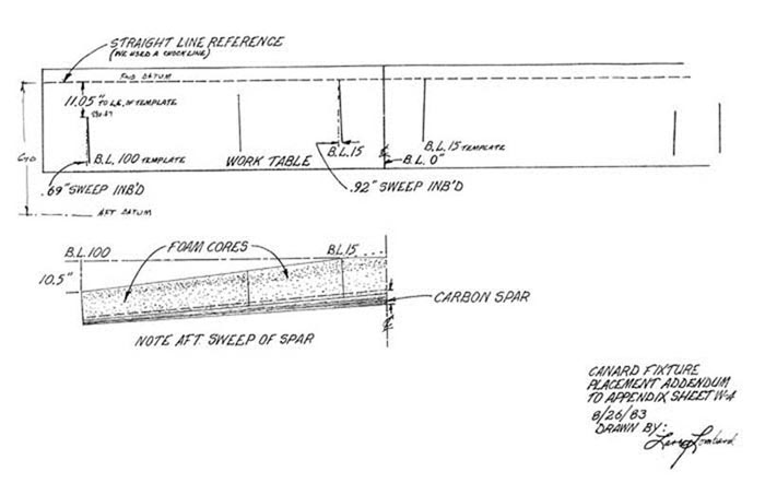
Addendum to Appendix Sheet W-4 8/26/83
Note: The sweep is established by the placement of the BL15 and BL100 Template Jigs on the work table. Once they are fastened to the table, trial fit the spars. The BL48.8 Template Jig should not be used until AFTER the spars have been permanently joined.
Once your jigs are in in place, go ahead and dry-fit everything just to see how it all looks.
NOTE: BL100 blocks will extend slightly outboard of BL100 foam cores since foam core measurement was flat, not at anhedral angle. You can move the BL100 jig blocks inboard to match the cores when trial fitting to spars.
JOINING THE SPARS
Trial fit both spars at trailing edges (we held ours in place with large rubber bands). Some custom fitting will likely be needed @ BL0-0. Note: 3.5°+ sweep aft of spars at outboard tips.
Sand spars completely for bonding. There is an extra ply of fiberglass on the surface for this purpose. You may want to use a powered sander, just be careful. Grind center portion of spars (BL 0-0) at apex to minimize bump. Wear a dust mask when sanding the black carbon fiber. *See 1st sketch page 2.
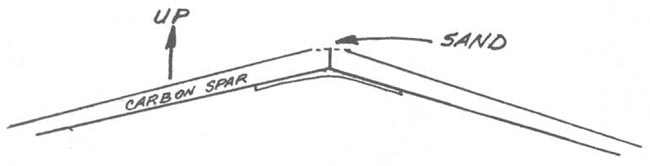
1st Sketch From Page 2
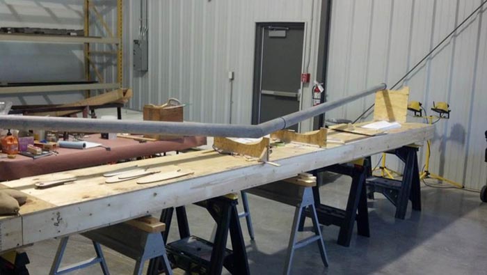
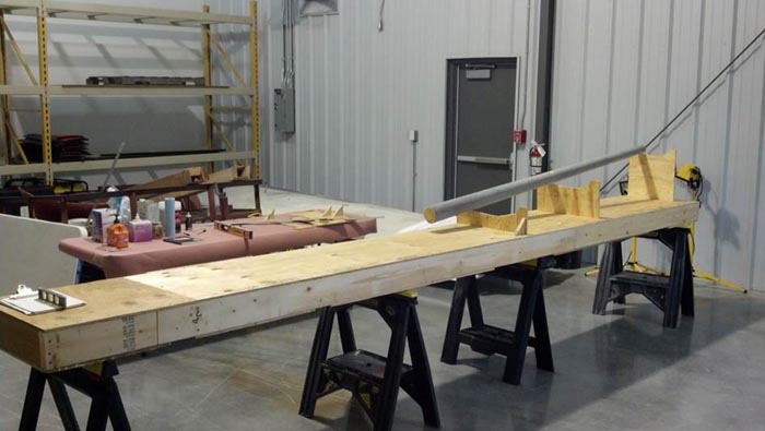
Jigging the Spars
Set the spars in the jigs and verify their fit. Remember the spars must join together perfectly in the center with no joggles. Tack one spar to the jig templates using the hot glue gun. The jigs at BL15 & BL100 establish the position and sweep of the spar, therefore at this time the jig at BL48.8 is unneeded.
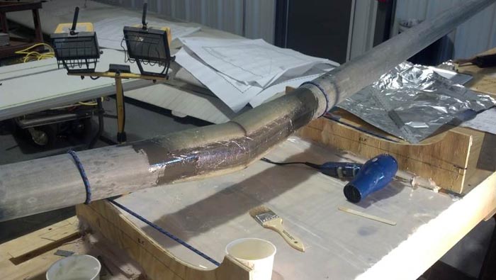
Then, coat the inboard ends of the spars with liberal amounts of flox. Join the spars at the center, ensuring good flox squeeze out. Wipe the excess flox off and, again, ensure there are no gaps. When everything is perfect, use bungees to hold in place and tack the second spar in place with the hot glue gun. Wait until the flox has cured and sand smooth. Do not break the spars out of the jigs yet. Be careful when handling, at this point the joint is still relatively fragile.

Center Spar Laminations
Next, the caps are laminated using UNI cloth. These caps are a minimum of 3-1/2" wide and may be laminated, five at a time, on a clean plastic surface (Such as Saran Wrap) prior to transferring to the spars. Since these tapes are narrow and short, you may find it easier to use the selvage edge for one side of each ply. This will reduce the fraying. Heads up! If you forget to remove the saran wrap the joint will be useless.
You will first, laminate the spars together with 3 ply BID wrapped all around at 45° extending about 6" either side of the center joint. Stagger the plies about 1/2" to 1".
The lamination schedule for the caps is:
Bottom:
§ 5 ply - 18" x 3.5"
§ 5 ply - 16" x 3.5"
§ 5 ply - 14" x 3.5"
§ 5 ply - 12" x 3.5"
§ 5 ply - 10" x 3.5"
Top:
§ 5 ply - 20" x 3.5"
§ 5 ply - 18" x 3.5"
§ 5 ply - 16" x 3.5"
§ 5 ply - 14" x 3.5"
§ 5 ply - 12" x 3.5"
§ 5 ply - 10" x 3.5"
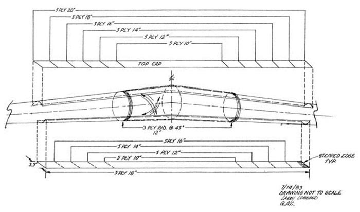
LS1 Spar Cap Lamination Schedule
BUILDERS TIP:
Cut all spar caps prior to laminating, and get organized.
Cut out all of the spar caps before you begin.
Get organized! This is going to take a couple of hours even if you have help!
Since so many pieces of glass are used, this layup can take a couple of hours. It would be advisable to have someone mix epoxy for you. You may choose to do the top and bottom caps in one session, using the Saran Wrap method described above.
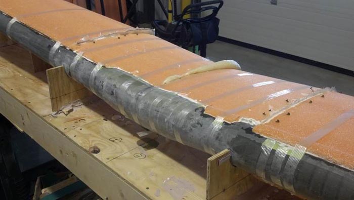
This photo shows all of the spar caps in place TOP and BOTTOM.
Once the laminations are complete, carefully wrap the entire lamination with PEEL PLY. Be careful not to disturb the alignment of the caps. You will probably need to cut several pieces of peel ply to accommodate the taper.
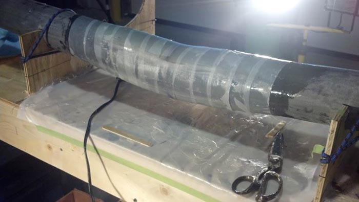
Wrap everything in PEEL PLY when all of the spar caps are in place.
Let everything cure for at least 48 hours before removing from the jig. When you return in two days, do NOT forget to remove the PEEL PLY!
Keep everything warm for a couple of days. Make sure the temperature does not exceed 100 deg. F.
After the caps are cured, sand as necessary for bonding the skins, though if you used peel ply, the sanding will be minimal. The center section foam cores will need to be opened up a bit to allow for these caps.
The level lines on all cores must remain perfectly level at all times. This is important, so take your time.
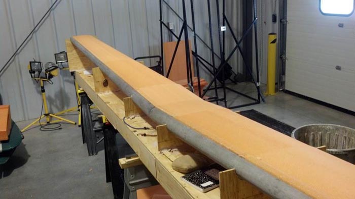
Stand back and sight span wise along the canard to verify that the canard is straight, and is not bowed or kinked. Verify that the leading edges are straight, and that the trailing edges are straight also.
Don't be concerned if the canard core female jigging templates need to be moved inboard or outboard to remove any bows or kinks. Also, a long straight edge will help you looking for kinks and joggles, or dips.
When everything is perfect, mix up some bondo (or use the hot glue gun) and carefully attach the canard core female jigging templates to the table top in the necessary location. Next, rest the canard cores on the canard core female jigging templates.
Outboard Canard Foam cores placed in the jig, as a trial fit, and checked for level.
Note: it’s time to remove the peel ply from the center of the spar!
Check the alignment and individual level lines again; then again and again until everything is Perfect, with a capital P. The next step is to join the foam cores together with micro slurry after verifying that the core fit is within 1/16".
|
CAUTION |
|
The canard foam cores must fit within 1/16" or exothermic damage may result. Core preparation is the single most important factor in obtaining an accurate, strong, and lightweight canard, so don't hurry through this section unless you don't mind regretting it for years to come. |
Place light tack masking tape along the spar to prevent micro and epoxy from migrating. You should remove the tape once the cores are in place, and before the epoxy has cured.
Paint the spar with pure epoxy and coat the inside cavity of the foam core with micro. Start with the BL0- BL15 cores. Use firm pressure to seat the core onto the spar and squeeze out excess micro
. 
Check, recheck, and re-recheck each core level line and alignment as the cores are joined. Recheck your level lines, and then tack the cores to the jig blocks using the hot glue gun.
Insert the BL48.8-100 core in the same manner, joining the two cores with micro slurry. Use large rubber bands, or filament packing tape, to apply continuous pressure. We want to make sure there are no voids. You should observe micro slurry squeeze out. Repeat for the other side of the canard and let cure for 24 hours.
You will need to open the spar cavity a bit to accommodate the LS1 spar cap laminations. You may also need to trim the BL0 joint where the cores join.
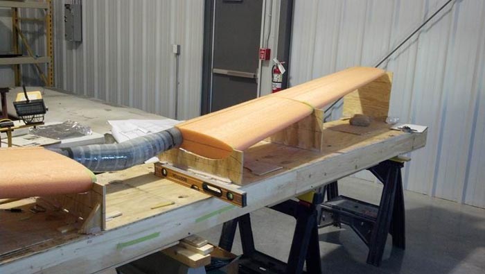
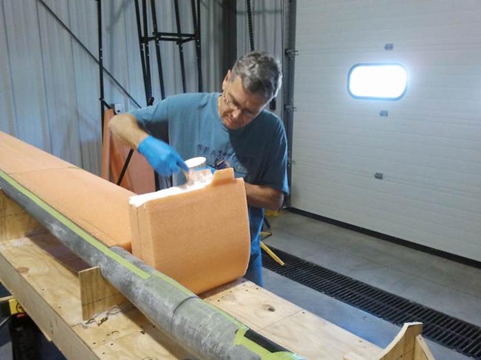
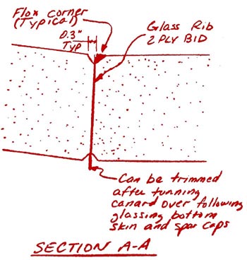
Note that the canard center section foam core gets a glass rib of 2 BID and flox corners at each end of the canard center section foam core. Laminate the ribs of 2 BID at 45° at the BL15 joints. Jig the BL15 to BL00 cores after the ribs are semi-cured (still tacky). The flox corner should be added after the entire series of canard cores have been joined and cured.
2 BID at 45° glass ribs being added to the BL15 end of the center foam core.
2 BID at 45° glass rib on BL15 end of the center foam core. (Opposite angle.)
BUILDER’S TIP :
In these photos we used filament tape to hold the cores in place. We found i t would be better to use rubber bands or bungee cords, since they will apply a constant force. Filament tape won ’t do that.
X-30 expanding foam is used to fill the gap between the foam cores after set-up .
BUILDER’S TIP:
Instead of using micro to join the two most outboard cores, use two-part expandable foam cores, use a good quality two-part expandable foam.
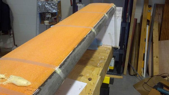
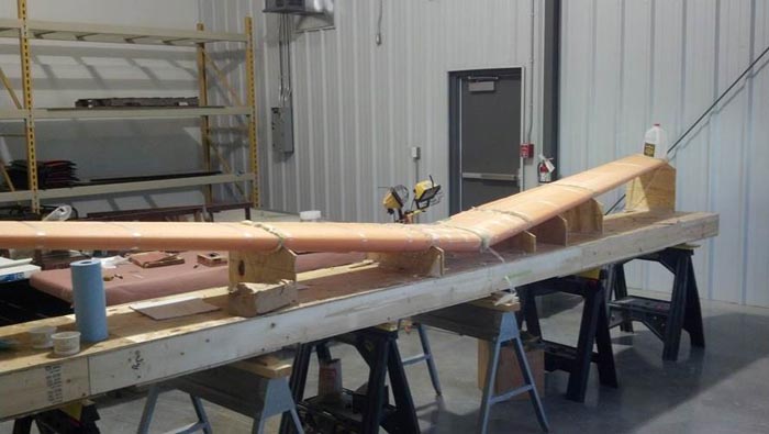
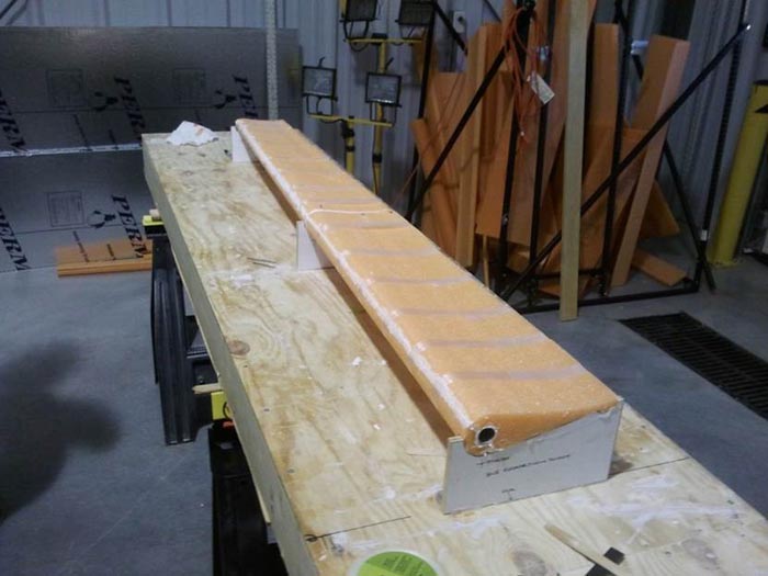
Canard on the jig table ready for cleanup sanding and prep.
Q-2 Plans: Page 10-2
PREPARING THE CANARD CORES FOR GLASSING
At this point, the canard cores should be jigged on your jigging table upside down, 5-minuted or hot glued/bondoed in place, and able to take a direct hit from a 88 mm howitzer without budging from its location.
Use a sanding block to clean up all joggles, excess micro, and any bumps on the canard cores. At either end of the canard center section core, round the joint so that the glass will flow smoothly across the joint.
This is your last chance to do it right, so spend at least another hour making these cores as perfect as you know how. While you’re at it, check, recheck, and re-recheck all the canard level lines that you can see until you can do it in your sleep. If you are not proud of everything sitting on that jig table, don't go on to the next step until you are.
Sand off the tabs on the cores tangent to the spars. Fair the surface of the core to the caps with very dry micro. Do not get any micro on the caps.
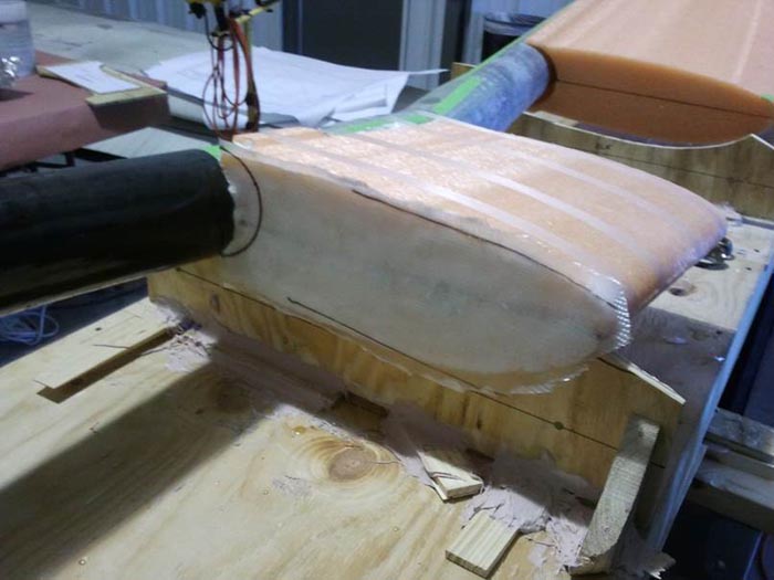
When the center cores have cured, you will notice a joggle where the foam transitions to the LS1 spar caps. The photo and description in the original LS1 construction addendum shows this joggle being filled with X-30 expanding foam. Experience has shown this to be a BAD practice as delamination can occur , so instead use very dry micro to eliminate the joggle.
Center joggle and foam core trailing edge tangent to the spar are filled with dry micro and sanded smooth.
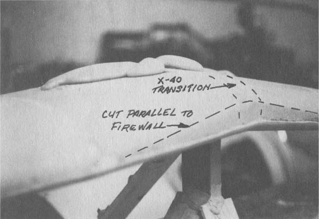
Fill Gap with X-40 - Sand L.E. Flush with Firewall. DO NOT fill the joggle with X40 as shown in this original plans photo.
However, you should sand the LE flush with the firewall as shown.
Note: Center blocks (BL15-'0-0') are shown with straight leading edge. BL15-BL0-' blocks should be parallel to firewall at leading edges, thus eliminating the sweep in that area. You can hand shape the inboard blocks since surface contour is not a critical flying surface. You should verify that you have removed enough of the LE. Find your CS14 pivots and tape them roughly in place. See QAC Chapter 10 (A) Elevator Control Addendum.
Go to the fuselage and measure the distance from the front of the fuel tank to the firewall. Now, measure from the aft end of CS14 to the LE of the canard and compare the two to make sure you will have enough clearance between CS14 and the fuel tank, once everything is glassed and the canard is mounted.
Do a final check top and bottom of cores for transition errors, warpage, etc. Place additional support members (blocks 31.9 & 74.4) in appropriate positions to assist core support for glassing. . .
Hold Everything together with T-pins and Rubber Bands...
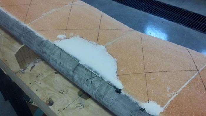
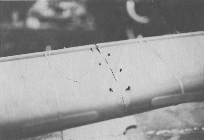
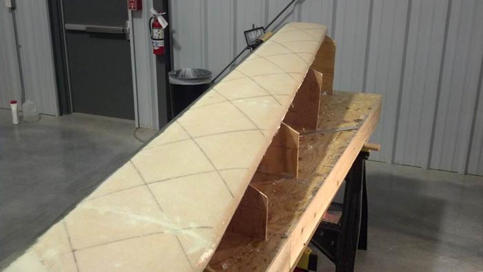
. . . We made random felt pen marks on cores ±45° to assist unidirectional cloth alignment.
Felt pen marks on cores ±45° to assist UNI alignment
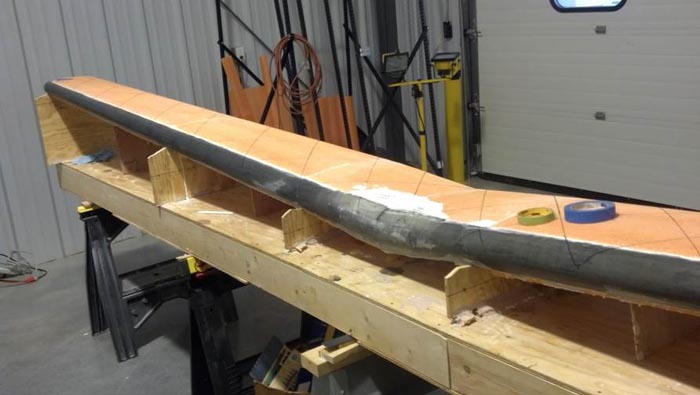
Canard ready for micro with ±45° lines drawn to assist UNI alignment. Additional jig templates have been added to help support the foam blocks during glassing and the cure cycle. You will also need to trim the leading and trailing edges of the jigs so you have room to drape the glass tangent to the LE & TE.
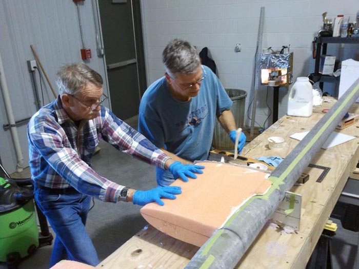
A note about organization for the layups. At this point, you should have your cores perfectly jigged in place and your spar caps cut, marked, and set aside in a clean location. (I like to use a magic marker to draw a center line on the spar caps). I recommend having at least four people helping for the layup. One person strictly for mixing epoxy and micro. Apply Micro to the entire canard foam cores .
Canard after micro application.
THE LAYUP:
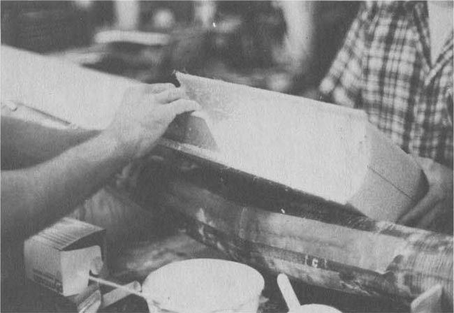
Better conservation of cloth can be employed by fitting scrap triangle with selvage edge inboard for first pull. (e.g.)
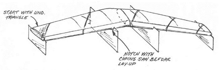
Scrap Triangle of UNI to Start
Allow UNI to wrap spar at T.E. and let cloth drape tangent at L.E.
Canard skin lamination schedule:
Bottom -
§ 2 ply at 45° to the spars (90° to each other)
§ 1 ply span wise
§ Overlap the spars with all 3 plies outboard of the caps and overlap the caps.
§ Knife trim the skins at the leading edge. After curing, sand to taper the skins between 0 and 1 on the hotwire templates.
Top -
§ 2 ply at 45° to the spars (90° to each other)
§ 1 ply span wise. We let selvage edge parallel L.E.
§ 1 ply span wise to BL15 each side for extra "heel" protection. Overlap the spars and the bottom skins on the spar by about 1 1/2". Overlap the caps. Overlap the leading edge of the bottom to about 1 1/2 on the hotwire templates.
§ Knife trim leading edge, let cure 24 hrs.
BUILDERS TIP:
You may either pre-cut the 45° UNI Laminations or you may cut as you go:
A. PRE-CUT: Make construction paper templates of the laminations, and then transfer to the UNI. Carefully mark these for placement on the canard and set aside.
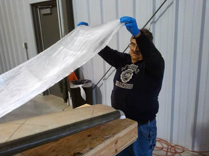
B. CUT AS YOU GO: Requires 3 people but is simpler. After you have applied micro to the entire canard foam cores and, have 1 person hold the roll of UNI cloth over the canard. The other two people hold opposite edges of the cloth and align the selvage edges with the 45° lines on the foam. Trim in place as you go. (See photo below)
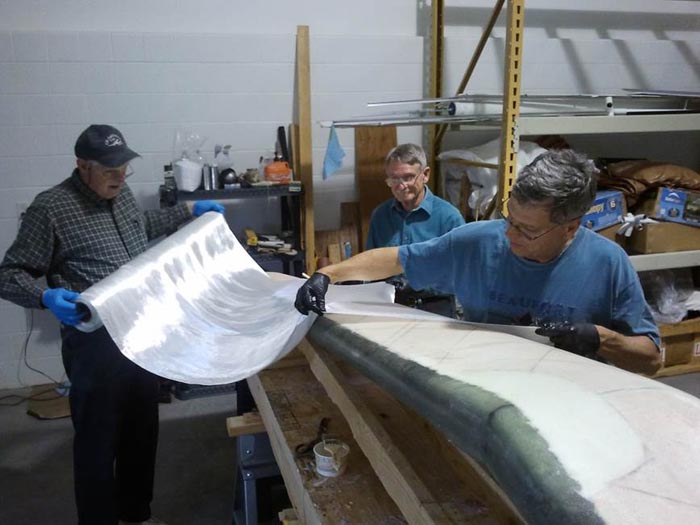
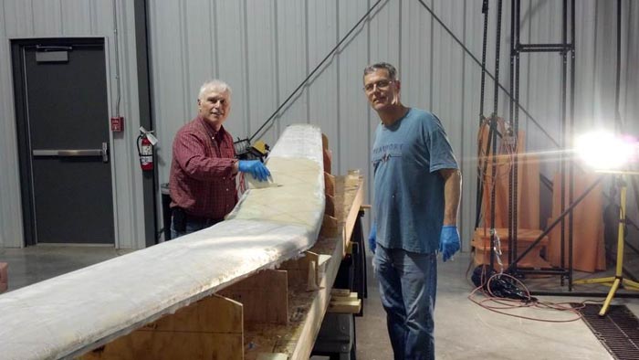
These three fine individuals are demonstrating the “CUT AS YOU GO” method of applying UNI cloth to the upper surface of the canard.
Applying the span-wise UNI spar cap.
Wetting out the span wise UNI.
BUILDERS TIP:
Experience has shown that additional UNI spar caps may be required, on the top side of the canard, to prevent dimples from appearing in the upper surface of the canard. See the addendum at the end of this section.
BUILDERS TIP:
After the laminations are complete, be sure to peel ply the spar, where the trailing edge cores will be attached.
BUILDERS TIP:
Some builders have had success by applying peel ply to the entire surface of the canard, after the final glass layers are applied. This is easily accomplished by using DACRON wing covering fabric. It may be useful to cut several pieces in 12” x 24” or larger sections. Make sure you have some overlap of each piece to facilitate peel ply removal.
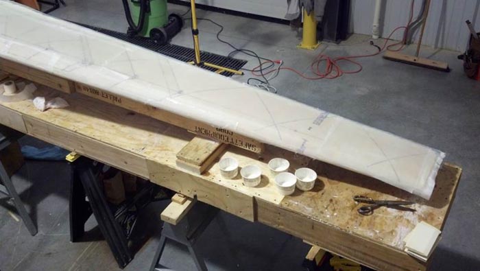
Celebrate the layup and let it cure at least 48 hours at room temperature before you disturb it.
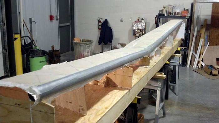
Bottom Glass layup completed, with PEEL PLY covering the entire surface.
FLIPPING THE CANARD OVER:
Use lumber as shown in the Q2 Plans before turning the canard over. Not as much will be required due to the stiffness of the spars.
Q-2 Plans: Page 10-4
Build a framework out of scrap lumber and bondo to hold the canard jigged in place while you turn it over. As shown in the pictures in the MAIN WING chapter in the "Laminating The Top Skin And Top Spar Caps" section, we suggest that the lumber run from tip to tip with a few cross pieces. Don't get fancy; just tie everything together so that the main wing won't move.
Check the canard tip level lines. Jig, and shim, and bondo until the canard tip level lines are absolutely perfect; almost, or maybe, doesn't count. Then use bondo to secure all of the jigging so that a jackhammer will be required to remove the canard from the jigging table.
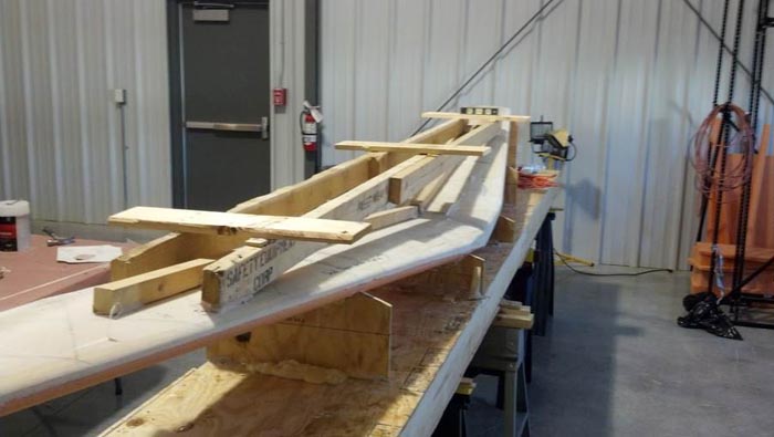
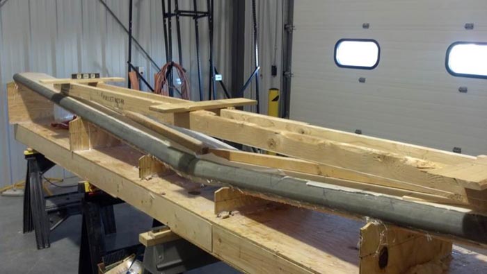
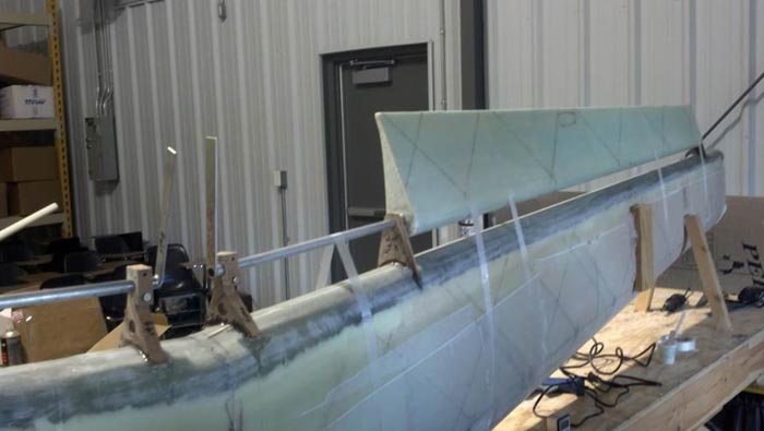
Temporary lumber framework attached to bottom of canard with bondo to facilitate flipping it over and glassing the top surfaces.
Next, (when you are sure of your framework) break the canard core female jigging templates loose with a hammer and chisel(they won't be needed again), and turn the canard over so that the unglassed cores are upward. Set the canard on the jigging table once again.
This photo shows the canard flipped over in preparation for work on the top surfaces.
NOTE: The temporary lumber framework is still attached
Prep and glass the TOP surfaces of the canard foam cores just as you did with the bottom. Cover everything with PEEL PLY (as you did on the bottom) after your final layer of glass, allowing overlap s to facilitate PEEL PLY removal later.
Again the TOP Canard skin lamination schedule (for your convenience):
Top -
§ 2 ply at 45° to the spars (90° to each other)
§ 1 ply span wise. We let selvage edge parallel L.E.
§ 1 ply span wise to BL15 each side for extra "heel" protection. Overlap the spars and the bottom skins on the spar by about 1 1/2". Overlap the caps. Overlap the leading edge of the bottom to about 1-1/2” on the hotwire templates.
§ Knife trim leading edge after a couple of hours. L et the whole thing cure for at least 48 hours before you break it loose.
BUILDER’S TIP:
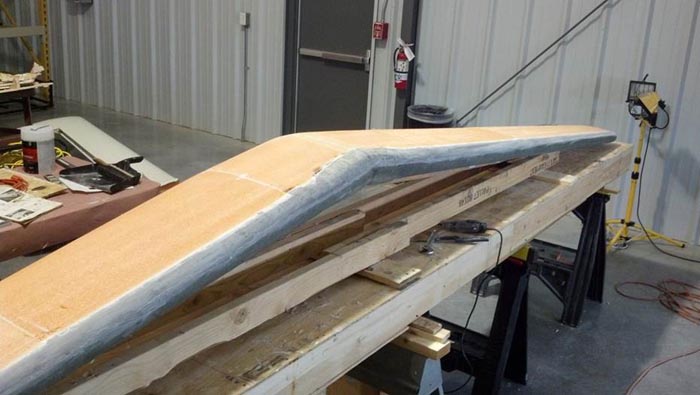
Experience has shown that several Q-200 aircraft have experienced some dimpling of the upper surface of the canard. While not fully understood, it is not believed that minor dimpling creates an unsafe condition. Some builders have elected to strengthen the upper surface of the canard, which seems to help.
Optional Builder’s Tip - Stiffen Upper Surface of the Canard
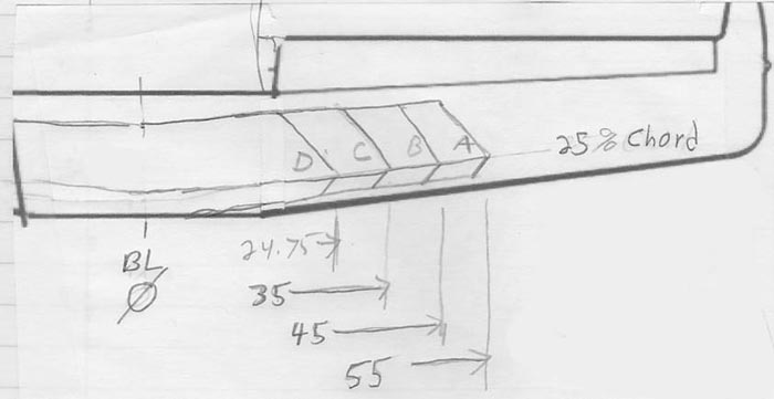
This builder made his UNI caps about 13” wide and stepped each about 3/8” aft. The “point” of each caps forms a 90 deg. angle. The point is at the 25% chord line.
BUILDER’S TIP:
You will need the elevators to continue to the next steps. You should build the elevators before the canard.
INSTALLING THE ELEVATOR MOUNTING ATTACHMENTS
Now we will install the elevator mounting brackets, before we install the slot cores.
OUTBOARD ELEVATOR PIVOT ASSEMBLY
..... These instructions cover only the assembly of the left outboard elevator pivot, but the right outboard elevator pivot is a mirror image, and may be accomplished at the same time.
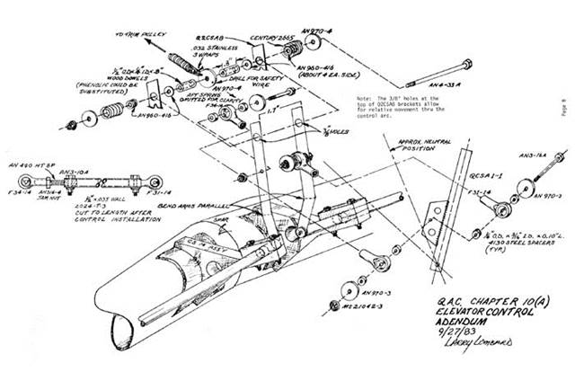
.....First, review the MAIN WING chapter section on "Outboard aileron Pivot Assembly". Except for the part number changes, you will be doing exactly the same operations. It is suggested that you install the CS14, CS15 & CS19 elevator mounting pivots before you install the slot cores. After the slot cores are installed you will install the CS17, mid-span pivot.
If you haven’t already done so, locate a QCSM7 pivot about 0.25" inboard of the outboard end of the elevator using 3 MSP43 cherry rivets spaced radially at least 0.4" apart. It will be necessary to "tunnel" through the elevator skin and elevator foam core in order to reach the CS16 elevator torque tube for riveting. The holes made by the tunneling operation should be filled after riveting with dry micro.
.....Find CS19, and insert a QCSM5 stud with the 2 AN970-4 washers, 1 AN960-4 washer, and 2 AN363-428 nuts, just as you did on the aileron outboard 'pivot assembly. Remember, there must be a minimum of 0.6" from the AN960-4 washer inboard to the end of the QCSM5 stud so that the elevator must be moved inboard at least 1/4" before it "falls off" the QCSM5 stud for disassembly. Finally, round the end of the QCSM5 stud slightly to assist in mounting the elevator.
.....When the elevator is mounted, CS19 will fit against the canard spar.
.....Do you understand? Good, read the above explanation again two times until it is indelibly etched in your memory.
.....Now you are ready to do the same thing for the right elevator. Remember that the QCSM2 pivot assembly, complete with QCSM3 stud, must be pushed into the CS16 elevator torque tube with the stud pointing OUTBOARD. (A mirror image of what you have already done). Be very careful in setting up the right mid-span elevator pivot assembly, and verify that it, too, will function as described in the paragraph above.
INSTALLATION OF THE ELEVATORS
The elevators are installed and rigged prior to the installation of the slot cores and the canard being mated to the fuselage. As a result, after mating only CS13 needs to be hooked up for a functioning pitch control system.
The procedures detailed here are similar in scope to what you have already accomplished in mounting the ailerons on the main wing, except that the elevators have a center pivot on each side.
Begin by jigging the canard perfectly vertical, with the leading edge at the table and securing with bondo.
Take a piece of QCSM1 and make two 1.8" 1ength pieces to slide inside the elevator as reducers. A saw cut and perhaps some light sanding will be necessary to make them fit snugly and flush with the inboard ends of the two elevators. Verify that Q2CSA8 will slide into the reducers and through CS15 with a minimum of clearance and play.
Find the phenolic bearings CS15 (2) and CS14 (2). Dull the phenolic completely with sandpaper except inside the reamed 5/8" diameter holes. Be sure that the other 1/2" diameter holes have been drilled out. These are non-critical on diameter, but must be there to assist bonding of the phenolic to the structure. They are NOT lightening holes.
A little about the order of construction is in order. You will first position the CS15 & CS19 pivots in place and secure with flox (permanent glassing will come a little later). Next, CS14 will be installed, followed by the installation of the elevator slot cores, and finally, the mid-span pivot.
The right and left elevators are mirror images of one another. Each elevator has an outboard hinge CS19, a mid-span hinge CS17, and an inboard hinge CS15. Q2CSA8 slips into the elevator reducer at the elevator end. These procedures were developed to help you get the elevators mounted without binding, with the proper clearances, and with the ability to get them off again.
First, we will locate CS15 on the canard. To trial fit, make a mark on the canard at BL18.5 on each side of the canard. The inboard face of CS15 will be placed at this mark. Now, go to the fuselage and verify that you will have clearance between the elevator and the fuselage. This is a preliminary fit just to get you started. You may want to tack CS15 in place with a bit of hot glue or even tape, until you know everything is positioned correctly. Measure from the outboard face of CS15, outboard 73” and make a mark. This will serve as the inside face of the outboard pivot, CS19. Ensure that the level lines on CS 15 & CS19 are correct.
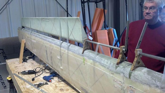
When you are satisfied that CS15 & CS19 are in the proper BL position, install the elevator use the LS1 elevator jigging templates to adjust the pivots radially about the spar. It may help to tack CS14 into place. This will take a while and you will need more than just your two hands. This step is critical to making sure the airflow over the canard flows properly into the elevator. Use both the templates and the level lines on the pivots. Note: slot cores are shown for reference only. Do not install the slot cores until the pivots have been completely mounted. Make and trial fit elevator spacers, which have a nominal length of 1.0" each. The actual length should be sized to allow the elevator to have a lateral free play (i.e. inboard to outboard) of about 0.05". Assemble each elevator, and again check for binding, misalignment, or excessive free play.
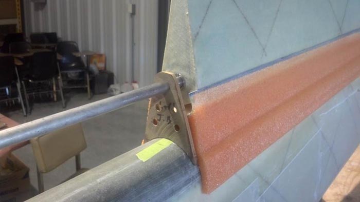
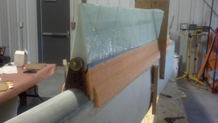
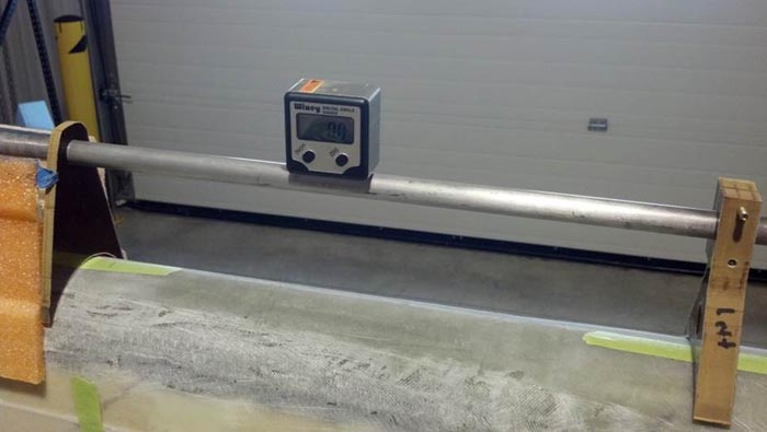
As you are doing all of this, you want to maintain perfect alignment of the Q2CSA8 with the rest of the elevator. We used a digital reference level to ensure that Q2CSA8 was exactly parallel with the spar. You will need to raise or lower CS14 to achieve the alignment.
Once everything is perfect, flox the pivots into place and let cure overnight. Now would be a good time to once again verify that the inboard end of the elevators will have clearance to the fuselage. Ensure that alignment remains perfect and that the elevator rotates freely. Carefully lay up the BID cloth that permanently holds CS19, CS15, and CS14 in place. These parts must be solidly mounted so that they cannot break off while in service. Use the "Aileron Installation" section of the MAIN WING chapter as a guide to the laminations. After you verify that the pivots didn’t move overnight and are still perfect, permanently attach the pivots to the spar with two ply of BID on each face.
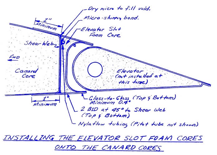
ELEVATOR SLOT CORES:
To start out with, the elevator slot foam cores that you hot-wired way back when were purposely made longer than necessary. Place the trailing edges of the slot core templates at the edge of the foam blocks and hotwire only the elevator slot areas. Next, glass the inside flat area with 2 BID. NOTE: Put down some peel ply in the area shown before glassing. Let cure. Do not glass the side where the spar goes.
Once the inner slot has cured, complete the slot core hot wiring. Dry fit your slot cores into the space between your elevator pivots. It will be necessary to trim the outboard of the outboard slot core to fit.
Now, you are going to repeatedly install and remove the elevator to as you trim the TE of the slot core. Work slowly as you trim. Keep trimming until you have about 1/16” clearance between the inner slot and the elevator.
The important point to remember is that the top and bottom of the elevator slot foam cores should flow smoothly into the top and bottom surfaces of the canard, respectively. If the elevator slot foam cores want to stick up a little bit, this is OK since that can be sanded later. Any dip, however, will have to be filled with micro.
Now it’s time to permanently attach the slot cores. You will paint the spar with pure epoxy and use a thick layer of micro on the slot core. We found it helpful to stuff shop towels or other soft material in elevator slot to enable the nose of the elevator to push the slot core down during the cure cycle. This will help eliminate any voids. Insert stirring sticks along the length, on top and bottom, to help maintain alignment and the 1/16” clearance.
MIDSPAN ELEVATOR PIVOT ASSEMBLY
..... Read this section carefully before doing anything, and take the time to visualize what the words are saying. Otherwise, you may find it difficult to install or remove your elevators!
.....These instructions will cover the left mid-span elevator pivot assembly, but the right mid-span elevator pivot assembly is a mirror image.
.....Find a QCSM3 stud and a QCSM2 pivot. Screw the QCSM3 stud into the QCSM2 pivot, retaining it with AN363-1032 locknut, making sure that the assembly is tight. Next, round the end of the QCSM3 stud slightly, as shown, to facilitate installation and removal of the elevator later.
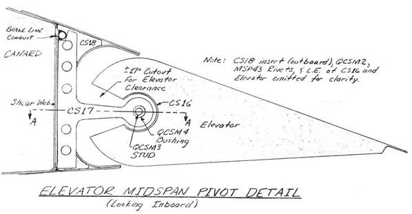
.....Measure 30" outboard on the elevator from the inboard end and place a mark. Using a router bit, route out a slot 1/8" wide for about plus or minus 17 degree of elevator travel. (See sketch – note, sketch is for the old GU canard, but the idea is the same.
Caution: Only open the elevator the bare minimum required. There has been a documented fatality where the builder took too much out of the elevator torque tube resulting in an in-flight failure.
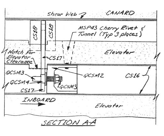
.....Next, insert the QCSM2 pivot assembly, complete with QCSM3 stud, into CS16, the elevator torque tube, with the stud pointing outboard. (See sketch) QCSM2 pivot assembly through the CS16 elevator torque tube with a small diameter stick until it just reaches flush with the slot that you routed out. Rivet the QCSM2 pivot assembly to CS16 using 3 MSP43 cherry rivets spaced radially at least 0.4" apart. Again, it will be necessary to "tunnel" through the elevator skin and the elevator foam core to reach the tube. Again, you will fill the holes with dry micro.
.....The routed slot must be expanded so that the CS17 hinge can slide off of the QCSM3 stud and out of the CS16 elevator torque tube while remaining perpendicular to CS16. This is to allow assembly and disassembly of the elevator. Probably, you will have to open the routed slot up to about 0.6" wide. Keep this opening to the minimum! At the same time, verify that the CS17 hinge can rotate at least 17 degrees up and down to allow proper elevator movement. If not, make the routed slot bigger, as necessary. It is important, however, not to remove any more "meat" from the CS16 elevator torque tube than necessary, so work carefully. .
.....Now we come to the 2 CS18 inserts. Make sure they have been made from the High Density foam, not the bulkhead type foam. These inserts are positioned against the canard spar on either side of the CS17 hinge, and provide a local beef-up to take the hinge loads. To determine exactly which BL the CS18 inserts must go at, you will need to trial fit the elevator in position in the elevator slot foam core, making sure that the inboard end of the elevator coincides with the inboard end of the elevator slot foam core that you have previously trimmed to fit the fuselage.
..... With the CS17 hinge mounted on the elevator up against the end of the QCSM2 pivot, and with the elevator in position in the elevator slot foam core, you can mark on the elevator slot foam core where the 2 CS18 inserts must go. Next, route out the foam in the elevator slot foam core in preparation for later bonding of the CS18 inserts in place. Any excess foam removed can be filled in later with flox during assembly.
.....Now, let's carefully review how the elevator is removed from the mid-span elevator pivot. The elevator is moved inboard, resting on the QCSM3 stud, at least 1" until it falls off the QCSM3 stud. During this movement, the CS17 hinge remains where it was, since it was permanently attached to the canard (between a sandwich of CS518 inserts) during assembly.
Once the laminations indicated in step 6 have cured, you will want to install the CS17's permanently. Install the elevators on the inboard and outboard pivots; remember to leave at least a gap of 0.5" inboard for the elevator spacers. (If you haven’t lost any inches anywhere up to this point. those spacers will be 1.0" in length). Install CS17 on QCSM3 against the face of QCSM2. Make CS17 the meat of a sandwich with a pair of CS18's as the bread, and trial fit the sandwich against the canard shear web dry through the slot made previously. When satisfied with the fit, and sure that the elevator clearance is a minimum of 1/16" top and bottom, permanently mount CS17 and the CS18's with wet flox. It is very important to really pack the flox into the holes so that you get very good squeeze out, and not trapped air. If the flox doesn't ooze out when CS17 and CS18's are pushed into place, then you haven't got enough flox pushed into the holes. Use tape and stirring sticks to maintain the 1/16" elevator clearance top and bottom while the setup is allowed to cure for at least 24 hours. Obviously, be careful that the excess flox does not interfere with the elevator movement, or bond the elevator to the shear web. If you previously removed the top and bottom canard skin where the slot was ground out, be sure to laminate 2 BID top and bottom once the laminations have cured. . The above procedures are used with both elevators.
It is recommended that you wait until the canard is installed on the airframe before you drill the holes that connects the elevator to Q2CSA8. When the time is right, find your elevator rigging template & reassemble everything, and set the elevators at 0 degrees. Also, verify that each elevator is pushed outboard against CS19. Verify that both Q2CSA8 overlaps into the elevator reducers a minimum of 1.8”. Now drill in very carefully the two bolts that fasten Q2CSA8 and CS16 elevator reducer together. BE CAREFUL! Don't let the holes elongate; use a small drill and work up in size. Also, be absolutely sure that each elevator is at the same angle (i.e. no asymmetry) and that full elevator deflection is available without any interference anywhere in the system.
The elevator slot foam cores are unique in that both the brake line conduit and the pitot tube must run through the lower, forward edge as shown on the sketch.
The pitot tube runs out the right canard, exits at about BL40. Be sure you use enough tubing, at each end, to reach their ultimate connection.
In the right canard, the brake line conduit enters the inboard end of the elevator slot foam core within 1/2" of the top edge, and continues all the way outboard to the end of the outboard elevator slot foam core on the right side of the aircraft. Let the Nylaflow tubing extend at least 24” beyond the end of the slot foam core. On the left canard, do the same routing. You should use a router bit or your Dremel to route out the foam. Any extra "room" in the foam is filled with dry micro or two-part foam. Both the brake line conduit and pitot tube are installed with 5-MIN dabs to hold them in place, and then surrounded with dry micro, as shown. You also may want to try making wire staples out of 0.042” safety wire. Keep both lines as straight as practical.
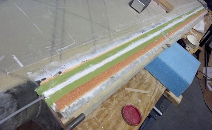
This photo shows a second tube, which is for the Angle of Attach indicator. This feature is only available with certain EFIS avionics.
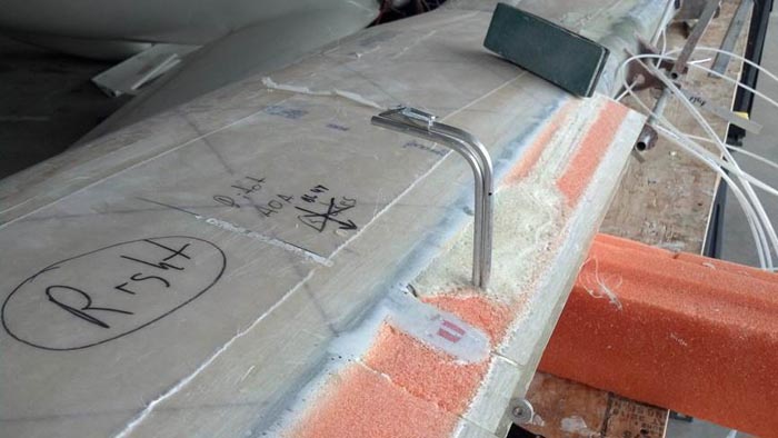
Next, sand down the slot core "tails" so that you can achieve a minimum of 0.4" of glass-to-glass bond with the inside lamination., while at the same time fairing everything nicely into the canard contour forward of the spar. At the glass-to-glass bond area, you must sand away all micro and epoxy and get down to the glass. Spend some time looking at the surfaces getting the best alignment that you can. When everything is ready, laminate 1 ply BID at 45 degrees to the canard shear web on the elevator slot foam cores, being sure to achieve at least 0.4" of glass-to glass bond, and lapping up onto the canard at 1 east 1". Note that the sketch ca11s out dry-micro fill if required at the top and bottom of the spar joint.
GU canard shown below for reference.
POST-CURING THE CANARD STRUCTURE
..... In order to minimize creep in the canard, the canard should be post-cured prior to installing it on the aircraft.
.....Creep is the tendency for the epoxy to deform due to heat and load. In the case of your aircraft, the heat could be obtained on a hot day with the aircraft setting in the sun, and the load is always there when the aircraft is resting on its 'landing gear'. The loading through this means is both bending and torsional in nature.
.....Creep can be minimized by heating the structure to a higher temperature than it will see while in service. If you own a multi-million dollar corporation, you should use a very large oven with accurate temperature control throughout; if you are like the rest of us, you can obtain equal results by painting the canard black with primer and setting it in the bright sun to effect the post-cure.
.....If you desire, you may want to finish the canard up to the primer stage before post-curing it. (Note the surface waviness criteria in the finishing section of the Composite Materials Education chapter). However, if you desire to do all of the messy finishing work at one time, you can elect to just shoot some black primer on the canard, and clean it off later. It is important to remember that when you attach the canard to the fuselage later, wherever the BID tapes that secure the canard to the fuselage attach to the canard, the canard must be free of any paint, micro, feather fill, etc.; i.e. just the pristine structure.
.....The reason you will want to use black is that it makes the job easier by absorbing more heat, thus raising the temperature of the structure quicker. . The technique you will use is quite simple. Expose the top and bottom surfaces of the canard to the sun, changing the angle of the canard periodically to heat the entire surface. Check the temperature frequently by placing the palm of your hand on several locations. If you can hold your hand on the surface for about 5 seconds without screaming out in pain, the temperature is perfect. Permit the canard to set at that temperature for about 10 minutes. DO NOT PERMIT THE CANARD TO GET TOO HOT.
.....It is not necessary to post-cure any other structure on your aircraft.
You may also choose to build an oven to post cure your canard. This is relatively done using ½” foil backed foam board available from home building centers, such as Home Depot. It’s okay for the structure to be flimsy, don’t over engineer it. It only has to last about eight hours. We used drywall screws to attach it to the jig table, and duct tape to hold everything together. You should get at least three heat sources and plenty of fans to keep the air moving within the oven. Air movement is very important to avoid hot spots which may damage the foam. We also highly recommend using a thermostatic control to prevent overheating. You want 145F for eight hours. No hotter, no longer.
Get a thermometer and insert it through the foam in several places over the course of the cure. Monitor that you dont get any hot spots.
NOTE: There is a full write-up about how one builders created a post cure oven in Q-Talk #161:
http://www.quickheads.com/index.php?option=com_content&view=article&id=2362&catid=48&Itemid=101
SPARROW STRAINERS:
These are trim devices required due to the pressure distribution of the LS(1) 0417 Mod Airfoil. Through testing, we have found the most effective position to be inboard (both sides of course).
Construct as follows:
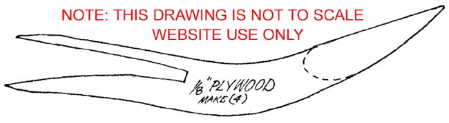
Make 4: 1/8" plywood stringers.

Also Make 2: 11.5" balsa wing sections.
5 minute epoxy 2 plywood stringers and airfoil section on elevator about 1" outboard from inboard but line. (duct tape and large rubber bands are helpful here). Make small micro radius at stringer attach to elevator. Cover everywhere with 1 ply BID. (We used a lighter weight tooling cloth available at most hobby houses - about 4 oz.) This cloth is also a good choice for antenna close-outs.
INSTALLING THE NEW CANARD
Installing the new canard to the fuselage will tax your imagination. Not unlike Chapter 12-2 of the Construction Plans, it may take several hours to trim and jig the canard to the fuselage and in reference to the wing. You should exercise extreme caution in leveling the fuselage in all quadrants and jigging the canard . (You did bond reference levels to canard while it was jigged for glassing, didn't you?)
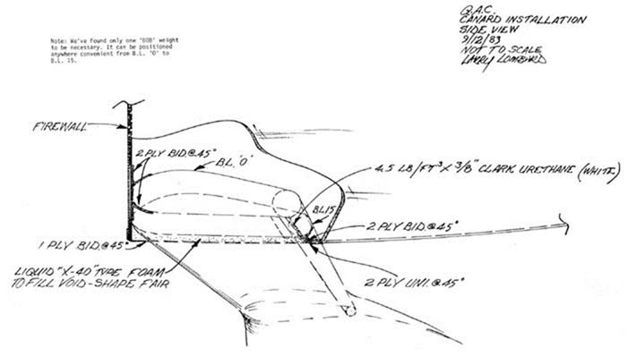
Please note: Your LS-1 mod canard mounts at zero incidence as opposed to the G.U. Also, without a straight center section as on the G.U., there is no bottom reference to the fuselage. Therefore, it would be best to have the magneto box cut-out completed as a reference to the apex of the LS-1 for final canard- to-fuselage assembly.
After canard is installed with liberal dry micro radius and 2 ply BID, micro transition blocks from fuselage bottom to canard (4# x 3/8" white urethane) and 2 ply BID inside and outside lapping at least 1" everywhere. (See drawings and photo.)
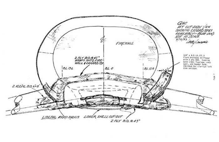
Then, with 2# urethane block or, better still, X-40 pour-in-place, fair bottom of fuselage cut-out to firewall and closeout with 1 ply BID @ 45°. You may also use the previously discarded piece of fuselage shell that you removed to install the canard. Attach with 2 BID.
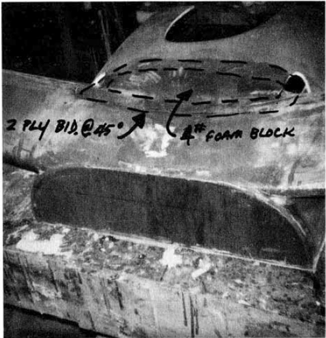
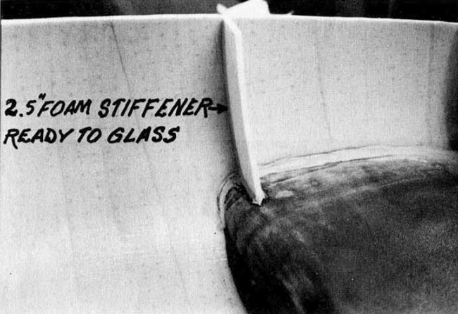
Next, install additional 2.5" stiffeners left and right sides of fuselage centered over spars as per drawing.