Q-talk 43 - LETTERS


- Details
- Category: Q-Talk Articles
- Published: Friday, 31 December 1993 06:11
- Written by Jim Masal
- Hits: 3257
Dear Jim,
My wife, Joanne and I really enjoyed the Ottawa fly-in last summer. The learning curve has greatly increased for me at the last two "Ottawa Events". Lot of the info traded there has literally saved my "Buns" and the "Gluteus Talfineus" of my Q2 also.
N83RJ was purchased from Bob Herman of Williston, ND and trailered home to Enid, OK almost two years ago. In the next two years I spent lots of time working, tweaking and wondering. Charlie, my hangar mate, noticed I was a little disappointed and said, "You've been spending most of your time on that engine". Well he was right but I've learned a few things in the process and I hope I can be of some help to other Revmaster owners. Steve Bennett of Great Plains Aircraft is probably the best advice I can give. He is top notch in VW conversions and overhauls. He rebuilt my Revmaster after the crankcase cracked while visiting Sioux Falls, SD. It's a long way to Sioux Falls from Enid, especially in a Datsun pickup with a trailer and a Q2. The people on the interstates really enjoyed being in our parade. Lots of Kodak faces. "Cool plane Dude ... does it fly or do you just drive it around at fly-ins or what?"
Here are some of the things Steve, Mica (A friend of mine) and I found wrong and then corrected.
1. The cooling baffling was inadequate. Mica and I built cooling boxes over the tops of the cylinders and heads (like the racers use). It channels and forces the cooling air directly to the spot where it's needed. We lowered my cylinder head temp. about 75 degrees from 400 degrees F to 325 degrees F. Halleluiah, no more aluminum in my sparkplug threads!
2. The VW 040 head worked better than the "old Revmaster 75 HP head." And I didn't loose any noticeable horsepower. Steve tooled in a smaller sparkplug in the bottom of the head leaving less chance of a crack between the plug and the valve.
3. Crankcases with the higher magnesium alloy % are more prone to cracking. We used case halves with more aluminum.
4. My connecting rods were 20 grams out of balance. Not good. Steve corrected.
5. The 75 HP heads increase horsepower mainly by increasing compression ratio. We lowered the ratio to about 8.6 to 1. Hopefully this will help to take some strain off the crankcase halves. There was no noticeable loss of horsepower.
6. The crank didn't pass the fingernail test so we had it turned and balanced at Scat.
7. The cam was not rotating the lifters so it was machined.
8. Steve also suggested I avoid "red lining" the engine because higher RPM produces higher horsepower and higher horsepower puts more strain on crankcases. Maybe cruise at 2900 to 3000 RPM.
9. Avoid full power prop strikes. It may not have caused the case to crack (I flew about 60 hrs after the strike) but then again it probably didn't help. It's also dimwitted and dangerous (Joanne won't let us say stupid at our house).
10. Retorque the head bolts at about 5 hrs after overhaul. Retorque periodically.
The engine had quite a few small problems that Steve was able to correct. Hopefully, I will now be able to fly it more than work on it. There were many other things to mention but Steve could say it better in his book.
Side note: Last fall my lovely wife and I took a break and flew to Galveston for R and R! When we landed the FBO person said, "Wow, cool plane ... but a yellow one just like it left earlier today". Was that you, Charlie Harris?
Anyway, pray hard, play hard, work hard and get lots of good advice. I'll see you in Ottawa! (Maybe I'll write a song.)
From: Bruce Crain, 2816 Meadowlark, Enid, OK 73703
ED NOTE: Yeah, and don't do anything stupid!
Dear Jim,
I'm sorry that I don't really have anything to report. The weather has been pretty much crap since the Labor Day fly-in. N17PF now has 305 hours (not bad, but I wish it were higher!). So I'll just give you my $20.00 (which is what you really wanted anyway, right?!?).
Hope to see you at Sun 'N Fun!
Sincerely,
Paul A. Fisher, Q N17PF
Ed. NOTE: Well yeah, I want the bucks, but what would they do me if I didn't have any info to print? I mean $20 bucks will only get me so far into Mexico! Anyway, you are not one I ever worry about reporting ... you do it plenty and we enjoy it ... and don't let friends fly metal airplanes!
Dear Jim:
My Q-2 has not flown much this year -- approx. 8 hours. I had to get rid of the Revmaster geared starter (didn't like the condition of it staying engaged if the engine didn't start). Steve Bennett came through with a GOOD starter and adapter plate (the Revmaster and Diehl accessory cases are not compatible). Since I had the engine off I had a valve job (252 hours) and the mags serviced -- they needed new points. The starter works great but my Revmaster engine continues to be a hard starter (from hour one to 252).
Then in May I obtained a Tri-gear kit from Scott Swing and started the project in June. Scott's reputation as a pillar to the Q-2 community has not changed -- he is eager to be of service and always takes time to hear you out. As of Nov, I have not flown with the Tri gear. The system is in, however, the problem is with the Matco brakes. I have been unable to get them to hold evenly on each wheel. The problem appears to be a binding in the sliding of the calipers on the spacers. Also, I'm still waiting for the FAA rep to give me a new airworthiness certificate. His verbal instructions were I could taxi it but not to get airborne and that he would restrict me to 4 - 6 hours within a 20-mile radius of the airport. Oh well!!
Here's a tip to you tail dragger Q-2 owners. While installing the Tri-Gear I had to reroute the rudder cables and noticed a slight play in the rudder. It appeared the bell crank bolt did not have a tight fit in the rudder tube. I found the bell crank bolt had grooves etched on the shank where it made contact with the bell crank. No doubt this was the result of vibrations and pressures on the tail wheel/rudder lash up. The tail wheel tends to skid or "skitter" on landings and this transmits a rapid back and forth torquing on the rudder bell crank/bolt/rudder. In summary -- pull that bell crank bolt and check it and replace it.
Anyone needing a set of new Cheng Shin tires give me a call.
Fred Wemmering, 5317 Maryland Dr., Fayetteville, NC 28311
(910) 822-2224
Dear Jim,
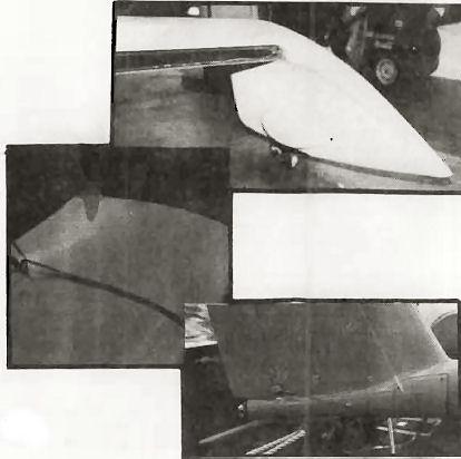
Here's the picture of my plane in Hays, KS on the way home from Ottawa that I promised to send. Sorry I took so long. I tore the engine down at Hays because of a serious miss that I couldn't remedy. I thought I had a stuck ring so the pistons and rings got cleaned in Hays during a weather layover. That turned out to not be the problem as the miss continued. Turns out it was something in the ignition. I replaced the points and condensers after I got home and the miss went away. I partially cured the miss on the way home by replacing the plugs but that wasn't the problem. The ignition was getting weak and would run (poorly) on fresh plugs but wanted new plugs every five hours. The Rotax tells you it wants something by going to one cylinder and forcing you to land. That is definitely not a good way to fly in poor weather at low altitude. Sure keeps you sharp on your awareness of nearby airport locations, though. Anyway, thanks for all of your efforts for us Quickie drivers over the years. I really enjoy the QBA. Also, thanks a bunch for the award down in Ottawa. It hangs in a prominent place in my family room. (ED. NOTE: Bob got Best Quickie award for his beauty with the sissy pink stripe.)
Robert Bounds, Grant, NE
Oh Perfect Editor,
Thanks for your finest newsletter yet. I think I got seven pictures and two letters. How much is this going to cost me? Anyway, I was about to get the DT's waiting for it to arrive. I just had to let you know how much I enjoy your work. Local news: Howard Hardy bought that Q-200 up in Wisconsin and proceeded to let it blow off the trailer on the way home. Broke his heart and I wanted to kick him in the butt except I know he'd already done that enough himself. What was amazing was how little damage there was to the airplane. He had the engine and tail off so all he really did was scrape the wingtip and deck and crunch the canopy. There were some funky things done with some of the plumbing and controls so he's going to fix them too. I talked to him last week and I would expect the airplane to be up and about in about two months. He plans to sell his Q-1 when he gets the Q-200 up and flying well. That would be a good one for someone to buy if they want a good Rotax Q. I'm still working on the Vari-Eze. Jeez, that thing is hard to build compared to a Quickie. If someone were to ask me which is better between a Q-200 and the Eze, I might have to say the Q. Don't let the nose-dragger crew hear me say that. Blasphemy! I think they both go about the same speed and carry the same load but the Q has more luggage room and is a bunch easier to build. The V-E is a better ground handler but if I can learn to fly a Q, anybody can. Both airplanes look strange enough to attract a crowd about anywhere but Oshkosh.
I still haven't been sold on the training wheel version of the Q-200. Looks too weird even for me. Harris stopped by a couple of days ago to drop off an 8 x 10 he took of me on the ride down to Kansas. Jeez, I'm pretty. He's a prince of a guy. I guess that's what I like about this association (including the D-Fly's). They're all great people. Ever notice how nice airplane builders are?
By the way, I heard somebody in Colorado bought the molds for the Q-200 fuselage and might start building a few. That's all you need is a rebirth of this plane with all the newcomer questions. Now you'll have to start earning that big salary you're getting for being our guru. (Hah) I've included my renewal check and my deepest gratitude for making our hobby (passion?) a little more enjoyable with your knowledge and enthusiasm. Fly safe.
Robert Bounds, Grant, NE
ED. NOTE: Oh, yeah, from time to time I hear about somebody who has those molds or some grand scheme of resurrecting the Q-2/200. It's amusing now. Don't hold your breath, for this business is full of wild-eyed dreamers with dollar signs where their brains should be. Show me the work and hardware 'n I'll get interested.
Dear Jim:
Enclosed are some random photos of some of the projects I've completed within the last few months. #2684 is a Tri-Q-200. I mounted the transponder antenna on the lower surface of the fuselage, just ahead of the MLG/Air brake door. Internally that locates it within the center console between the lower edge of the canted seatback and the aft edge of the main fuel tank. With considerable amount of difficulty I can reach the BNC coax connector from either the front or aft end of the center console but if I had it to do over again I'd build in access doors big enough to get your hand inside each of the two side armrests and the center console. These would've also provided access for installing BID tapes at the intersection of the consoles and the fuselage.
Next, I wanted to provide a means of elevating all wires, cables, etc. behind the instrument panel and the aft face of the firewall. These supports would span the horizontal distances between the magneto box and the inner surfaces of the fuselage at a WL several inches above one's feet when placed on the rudder pedals. I also wanted a support at the same level running fore and aft between the magneto box and the forward face of the header tank. To accomplish this I cut strips of 1 1/2 inch wide by 3/4-inch thick wood cut to the correct lengths, angles, etc. I rounded the parallel edges, covered the surface with Vaseline and covered three surfaces (two 3/4 and one 1 1/2) with three BID plies.
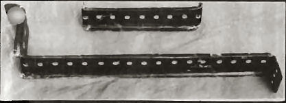
After curing and removal from the forms, I drilled numerous quarter-inch diameter holes along the center of the 1 1/2 surface to tie any of the components to a particular location along the support.
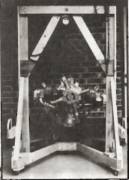
For a long time I'd been pondering how I would lift the engine from its storage dolly and install it on the firewall. I set out to design a hoist that would not only provide a replacement for the storage dolly but would also be capable of being operated by a single person during the engine installation and removal operations. The heart of my hoist is a $50 one-ton chair hoist I purchased from Harbor Freight in CA. I then built a "Gallows" truss to support the hoist and mounted the truss on a castered base with a "V" slot built in it so the base will clear the NLG during operation. It works GREAT!!!
I'm now concentrating on completing the many things associated with installing an O-200 engine in a Q2, i.e. the air induction system from the air intake hole in the cowling to getting the air into the throat of the carburetor. First I had to support the carb-heat-box (chb) at a convenient location near the carb and exhaust pipes. I, like so many of the other builders, decided that unlike the plans called for I would locate the chb forward of the carb and below the dual pipes from cylinders 1 & 3. I first attached the exhaust muff to the top inlet of the chb. This eliminated the necessity of having to utilize a section of conduit and two clamps. Next a 97-degree elbow, 2 1/2 inches in diameter had to be fabricated between the carburetor and the chb. One end of the elbow had to be compatible with the 4-bolt attachment to the carb and the other had to be clamped to the circular outlet flange at the rear of the chb. I carved the shape in foam and covered it with 4 BID plies. After curing I removed the internal foam, trimmed the flange to the required dimensions and drilled the matching holes for the carburetor. The next major consideration was what kind of an air filter should I utilize? I finally settled on a ring-shaped filter; 2 1/4 ID x 4 3/8 OD x 3 TK that has 80% more filter area than the standard Cessna filter for the O-200 engine. I wanted the filter assembly to be axial flow and with the filtered air entering the forward end of the chb.
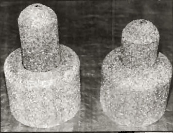
From two pieces of foam I carved two circular shapes shaped somewhat like potato mashers. The small diameters were 2 1/2 inches and the larger diameters were slightly larger than the OD of the filter. They differed from each other by approximately 1/8 inch to accommodate concentric overlapping during assembly. Again the foam was covered with 3 BID plies and after curing the foam was removed from within. A baffle plate was designed and supported in the forward end of the housing. The baffle directs the incoming air to the filter OD plenum chamber so the air can then traverse thru the filter and then exit thru the aft collar into the chb. The filter is sandwiched between the two housing components which are held together by two rows of three equally spaced screws.
A ringed collar with two opposing tabs was fabricated and installed on the inside of the cowling encircling the carb air inlet hole. Nutplates on the aft side of the tabs provide easy attachment to the inside of the cowling.
With the air filter housing supported from the chb and the ringed collar mounted on the cowling, the gap between is traversed with a short piece of CAT hose. The flexibility of the hose neatly accommodated the differential vibration between the engine and the cowling.
I bought a Cub 3-3 cabin heat box that I'm trying to think of a way to modify to control the internal damper in a way that's more compatible with my installation. More on that later. I'm also laying out the locations of all the hardware that mounts on the firewall, including wire and cable control penetrations. One good thing though is that I don't anticipate any epoxying during the winter months.
That's about it for now Jim ...
Dick Barbour #2684, 2405 Sequoyah Drive, Rogers, AR 72756
Dear Jim:
Enclosed is my renewal for 1994. I still believe QBA is a must for anyone building or flying Q-birds and I thank you for your commitment to keeping the association alive. I'm hoping my schedule will allow me to attend Oshkosh or Ottawa this year. I have about 60 hours on the Q-115 and I'm still thrilled with the results of all my efforts.
One idea that I incorporated into the plane was a unique standby fuel transfer pump. After flying for two years in the Q-2 version with the squeeze bulb, I tried to pump some fuel and found the bulb had become very stiff. I also discovered that pumping a gallon of gas even with a new bulb required the forearm of a weight lifter. I then considered a second electrical pump but was concerned that an electrical failure would transform both pumps to extra ballast. After considering a few other options I modified a Ford automotive fuel pump which I mounted to the bottom of the header tank so it can be operated by foot. When modifying the fuel pump I cut off all excess metal and drilled holes to lighten the unit (see photo).
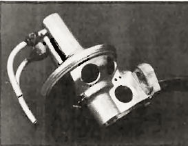
When installing the pump I recommend installing a stop so that when you push on the fuel pump lever you don't over-extend the diaphragm.
When using the pump be sure to allow the lever to return to its normal position before pressing on it again. The fuel is pumped during the return stroke of the lever.
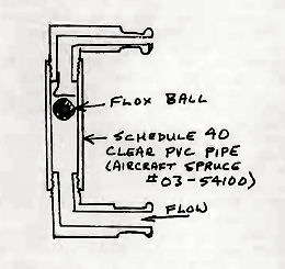
I also made a flow gauge to indicate if the transfer pump is operating. I used about 2 inches of 1/4" clear plastic pipe available through Aircraft Spruce and tapped the ends for threaded brass or aluminum fittings. From flox I made a ball just small enough to move inside the tube without binding.
One final reminder -- never lay an incandescent (ordinary) trouble-light on a wing, canard, etc. since the heat will melt the foam away under the fiberglass causing a potential structural failure. There will be no visible sign of the problem although tapping the surface lightly with a hard object and listening for a hollow sound sometimes works. The solution is to always use a fluorescent trouble light when working on fiberglass aircraft.
Hope my few hints save some members some trouble.
Kimbull McAndrew, Box 0 Site 19 RR1, De Winton AB T0l 0X0
0235 Conversion
I have not seen much written about how to put an 0235 into a Q bird.
I marveled at the performance of Kim's in Canada, and I am sure there must be a few more out there?
Anyway this is how I have set about my project.
My first priority was to try and keep the weight down as much as possible.
I intend if cash permits to use the Mt constant speed prop. This weighs 23.51 lbs so this and the heavy Lyc. gave me little choice but to move this mass as far rearwards as possible.
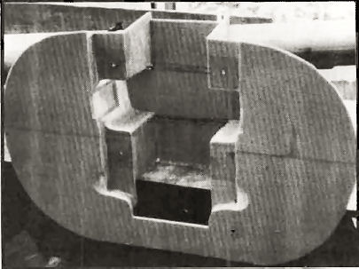
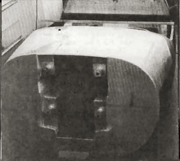
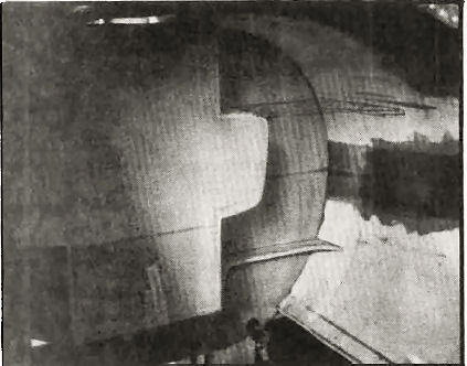
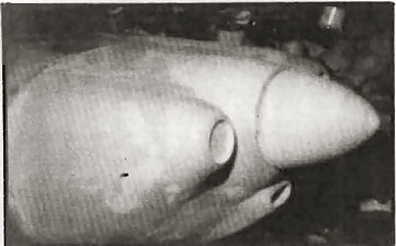
I figured the most I could practically move it back was 4" which should require only about 41 lbs. of lead at the extreme tail. This was achieved by moving the firewall back by 2" this meant taking 2" off the nose of the canard. The lost strength is to be regained by making an extra spar on the canard leading edge.
The firewall and the mag box was made from 10 lb. density foam, all covered with 2 BID and vacuum bagged.
I gained the extra 2" by mounting VW engine mounts 1" rearwards relative to the firewall, the pictures should make it clearer.