QuickTalk 30 - Q-2 HINTS
- Details
- Category: Q-Talk Articles
- Published: Friday, 31 October 1986 06:11
- Written by Jim Masal
- Hits: 4266
John Schnackel #2329, Fort Dodge, IA
COWL FLAP ACTUATION p. 16-5
The change suggested by QAC (Winter '84 Q2 BT) to positively actuate the cowl flap wouldn't fit because of interference with the intake manifold. I used an alternative system. The only material needed is aluminum angle iron or something similar. I used three-sided aluminum used as wall mounting pieces for shelving. Two pieces, one approximately 6 1/2", the other 3 1/2" bolted together to form a right angle. The longer piece is attached to the inside of the cowl flap with nut plates and screws; this is so the bottom cowling can be removed with the cowl flap attached to it. The corner of the "L" is near the cowl flap hinge with the shorter piece pointing up toward, but not hitting the oil cooler. The piece is just to the right side of the (Revflow) carburetor/air filter so it clears everything when actuated. The cable attaches to the top of the short piece. Pulling the cable handle will pull the short piece toward the firewall forcing the longer piece down, opening the cowl flap.

Regarding any proposed canard testing, since the canard is also the landing gear, it has to be much stronger than 4.4g. Early on I did some calculations and I think that when the canard is strong enough to be used as a landing gear, it is capable of nearly 12g of flight loads. This figure, based on the old GU canard, is mentioned in a very early review of the Q-2, I think. The main wing is much weaker and will stand only 4.4g or so.
From Saylor Milton
ED. NOTE: This drawing was left out of the tip described on page 13 of QUICKTALK #27. Solly, Cholly!

From Saylor S. Milton #2484
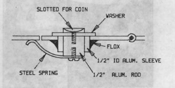
Here's a drawing of my latch for cowling dipstick and oil filler doors. While not quite flush with the cowling, it does not leak rainwater or air like some commercial latches do. It simply uses a coin for opening.
The materials used are .6" of 1/2" aluminum rod, drilled and tapped; .5" of 1/2" ID sleeve of aluminum tubing; a steel spring made from a bent hacksaw blade, (heat to bend); two screws, one with head large enough to file a coin slot; and a 970-3 washer. Use Loctite compound on both screw threads.
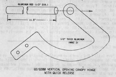
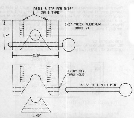
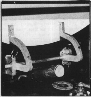
Here is my version of the vertical-opening canopy hinge and detail of emergency quick release hardware.
The 3/16" pins, purchased from a boat shop, are used to hold sailboat rigging together. There is a small spring-loaded tab on the end, which holds the pin in place. A quick pull on the two rings makes the whole hinge fall apart, releasing the canopy from the front.
Not shown are the mounting flanges for the base of the hinge and canopy mount.
I will send a full-scale template to anyone who sends a SASE and $1. Address is 1100 Cliff Ave., Filmore, CA 93015.
From Bob Falkiner
I decided to put a front opening canopy on my Q2 after another builder had his side hinge canopy pop open on a hard landing. Out of curiosity I phoned HAPI to see how the Dragonfly builders do it, and found out Mr. Taylor is adamantly opposed to the "C" type hinges that many people are using. These hinges can lock the canopy closed in an accident-preventing rescue, and eliminate the possibility of jettison when you or your test pilot figure the odds are better with a parachute. Mr. Taylor volunteered to send a copy of plans he made up, which I will forward on receipt. I decided to go with a "piano" type hinge, creating a reinforced 8" flat spot on the front fuselage. This is not a lot of work, and it took only a few hours in conjunction with a couple other minor layups. You can also make provisions to pull the wire hinge from inside or out for jettison or rescue. Note that the rescue provision is mandatory in Canada.
From T. J. Wright
We have built 4 Q-2's and have found the Quickie plans s____ as far as order of sequence to be installed. Our finding is that almost all the aggravation can be eliminated by installing the firewall and header tank in the shell top, installing EVERYTHING in the bottom shells, THEN install the top onto the bottom. Saves time and money.
From E. L. Puckett #2478
Has anyone designed a swing-away engine mount for the Q-2's Revmaster?
From
This arrangement worked very well for pulling the canard into position to seal. I had the fuselage leveled for wing installation and didn't want to change it. Two rods make it easy to get level and screw.
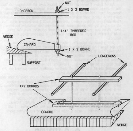
Materials: 2 1/4" threaded rod; 2 good 1x2 boards.
Pull up the back of the canard with nuts into cutout. Pull up for level canard with the wedge.
From Leonard Troutman, Fresno, CA
I have over 250 hrs. on N21LT and feel that Q-2's have a worse name than they deserve. A Q-2 can be flown by anyone who respects it in a crosswind and understands the forward CG situation. My plane must be flown on to the runway at 80 mph indicated. This is not that demanding to do - but no bounces, please.
Two things of interest from last summer's flying. First, the vortex generators DO work. On a trip to South Lake Tahoe and Reno I encountered light to moderate rain with only minor trim changes needed. Second, my tail spring broke while taxiing at slow speed last Labor Day. Thank goodness I was slow and at my home airport. At 80 mph on takeoff or landing, the best you could hope for is ONLY ONE broken airplane!
To repair the plane, I selected the steel spring (4140) from a Sonerai. Overkill, yes, but I sleep a little better now for only $65. After drilling out the glass spring to a depth of 9" with a 3/4" bit, I floxed a 9" piece of 4130 tubing, 3/4" OD into the hole and slipped the Sonerai spring into this tube. I drilled through the glass, 4130 tube and the spring for a 5/16" bolt to be able to remove the Sonerai spring easily.
I see a big improvement in ground handling during landings with this spring. The tailwheel now seems to stick to the runway because of the vertical hinge bolt. If I can be of any help to anyone, give me a call: (209) 291-4196.
I accidentally broke off my level gauge on the canard, so I made up two female FS48.8 female templates with level lines on them made from the hot wire templates, and glued on two 6" levels. Worked well
- has anybody tried a method of holding the hydraulic brake calipers off the disc when not applied?
From Larry Kehler #2531, St. Louis, MO
I promised Jim at Oshkosh that I would write a note about my observations concerning VW power for the Q-2. I have postponed the start of my Q-2 project for two years because I can't decide which engine is right (Mark that afraid to start). Gene has my engine deposit and I haven't been able to convince him that he should trade it for the new canard kit.
I attended the Auto Engine Development Forum and also heard Rex Taylor's presentation on the HAPI engine. I was impressed with the effort Rex has placed on head and valve improvement. I decided to conduct an informal survey on Revmaster and HAPI users that I could find at Oshkosh.
I talked to 9 Revmaster drivers and 10 HAPI drivers. The Revmaster users were mostly Q-2's and HAPI users were mostly flying Dragonflyers. The Revmaster reports were not very encouraging. 100% reported some problems. About half had upgraded to the new heads. All indicated that valve adjustment was very critical, requiring constant vigilance. One individual has had his engine down for months and after many phone calls, including one visit to Revmaster, the problem is not solved. The individuals who report that the Revmaster is "OK", condition the statement with "it is a car engine and not for aircraft use". I interpreted that to mean they didn't expect much and got what they expected! I talked to one Q-2 owner who was carefully checking his valve adjustment before leaving Oshkosh and said "he never felt safe flying cross-country with the engine."
The HAPI engine owners were much happier (sorry!) with their engines. None reported a valve problem and all reported that they would recommend the engine. The only complaints I could find with HAPI users were two overheating problems. They were solved by baffling changes.
I did find a Dragonfly owner who had valve problems and I was pleased to think I had found a HAPI complaint. It turned out that the engine was an owner converted VW and not a HAPI engine.
My conclusions are not what you are probably expecting. I decided that I definitely do not want a Revmaster engine but I don't think I want a HAPI engine either. For the cost of the HAPI engine I could have a 0-200 or better yet I saw a great Q-200 with a Lycoming!!!!
Dear Jim.
Haven't written in a while so here are a few tips to keep everyone busy.
1. When building the fuel filler door, I deviated from the piano hinge suggested in the plans. Instead, I used the hinge from a Datsun 280Z. The hinges on the Japanese cars work perfectly in this application and besides being readily available they are much lighter than their American counterparts.
2. I found a real easy, clean and lightweight method of attaching wiring, antenna cables, etc. to the composite structure. Amp-tie makes a self-adhesive pad used in conjunction with their Ty-Rap products. I start by removing the adhesive strip. Sand the plastic bottom and cover the center hole with a small piece of duct tape. (Just big enough to cover the hole.) Sand the glass where the attachment will be made and coat both the glass and the plastic with pure epoxy. Than put some flox on the bottom of the plastic and press in place. Remove the excess flox (but make sure it comes out through the mounting holes to allow for better adhesion.) After curing, use a Ty-Rap and that's it!/P>
Richard Kautz #2850
From Marvin Getten #2704
I enjoyed Oshkosh as usual, but I learned a lot about Quickies listening to Gene Sheehan talk to builders. Most complaints were about handling. I have had about a thousand landings with my plane, Velvet, and I haven't damaged it yet. The broken tailspring you reported was broken before we flew (I didn't wrap glass from the spring onto the tailcone and it broke during taxi.)
For good ground handling the aircraft has to be built properly. For example, in the tailwheel/rudder section where the plans show a tail wheel cable and the rudder cable in very near the same place, if the rudder is raised so the bell crank is a couple inches above the tail spring, the rudder cable will have an angle to the tail wheel section. When the tailspring is modified to get 7-8 degrees on the fuselage, this will create an adverse angle for the cables to the rudder. No wonder that bell cranks are being bent; if we bounce a landing the tailspring whips up and down. I can see where just taxi could stress the bell crank and I have seen a modified tail spring that bent when on the ground so much that at full right rudder the wheel was at the stop and the rudder was weather-vaned straight. There is absolutely no rudder control with the thing weather-vaned.
Now for the 7.5 to 8 degree ground angle of attack required on the Q-200 fuselage: the plans say to take the hump off the canard before you glass it. If you don't cut the hump enough, you cannot lower the fuselage down onto the canard because the mag box will hit it. It only makes sense that you will want to do this properly so you won't have to screw up the tail section to get 7.5-8 degrees. Cut the hump down and level (leave at least 3 inches) then put plenty of glass plies on - you will have level rudder pedals and a sturdy place to mount the phenolics.
From Fred Wemmering #2296
Finally got my Q-2 back to flying status after the tail spring broke on the first landing. What went wrong you ask? My opinion is I followed Q2PC9 dated 1 July 81 and had the 27" from floor to bottom of tail wheel. To H--- with the Q-2 ground angle of attack. If your assembly looks like the drawing on plans book page 14-2 you will twist off/break your fiberglass tail spring when making a high speed steering correction. What should you see when your Q-2 is setting on the floor? You should see QTW5 parallel to the floor and the AN3-22A pivot bolt perpendicular to the floor.
Some of the fixes I feel have helped tame this tiger are: (1) Rebuilt tail spring and tail wheel assembly using a Dragonfly tail spring and sleeve. (2) Installed vortex generators. (3) Built aileron reflexor. (4) Since my main wheels were mounted zero zero, I removed the axles, floxed shut the outside holes and redrilled that hole to establish a one degree toe out on each wheel. When facing the floxed hole go 7/16" to the right of the left edge of old axle hole and drill new 5/8" axle hole. (So what the H---, it worked for me.) (5) Established a tire pressure of 28 PSI. I haven't ground looped since these fixes; however, that tamed tiger is just waiting for his split second chance to grab my A-- on touchdown if I lose concentration.
Back in QUICKTALK #22 I published an Australian request for flight experience info from Q-200 pilots. This was desperately needed so that the Aussies could get approval to fly these models from their government. I'm disappointed that QBAers didn't help much as a group, but Daryl Johns, at least, was instrumental in getting approval for George Wills' Q-200 to fly. The following are letters to me from Daryl and George:
Dear Jim,
...I hope you will publish George Wills' flight experience with the Q-200 because it may turn out to be that of other builders. I know my first effort was not unlike his, but fortunately with better results.
I now have 180 hours on my Q-200 with successful flights from Vermont to Lakeland and Oshkosh with a planned trip to the West Coast.
I would emphasize in the strongest terms that the Q-200 should not be flown in any position forward of the center of the envelope. I feel George's experience must have been with a forward CG and thus the plane was totally unstable in landing. The reflexer would have helped, but this is a "fix" not a basic solution to the problem. My opinion is that the envelope we work with for the Q-200 is probably in error, given the heavier weights of our homebuilts. I know I had to add 15 pound at FS-165 in order to be in the center of the envelope. It would be helpful to have comments from others who are flying the 0-200 engine.
| Lt wheel...... | 333.0 lbs | ||||
| Rt wheel...... | 332.5 lbs | ||||
665.5 lbs | X | 36.5 | = | 24290.8 | |
| Tail............. | 11.0 lbs | X | 211.0 | = | 2321.0 |
| Ballast......... | 15.0 lbs | X | 165.0 | = | 2475.0 |
| _ | ___________________________ | ||||
691.5 | 42.1 | 29087.0 | |||
| Situation #1: | |||||
| Plane ....... | 691.5 | 42.1 | = | 29087.0 | |
| Pilot ....... | 170.0 | 57.0 | = | 9690.0 | |
| Header ...... | 30.0 | 27.0 | = | 810.0 | |
| _ | ___________________________ | ||||
891.5 | 44.4 | 39587.0 | |||
I remain in center or aft of envelope in all situations: full fuel and with passenger etc.
Daryl Johns N124DJ, Putney, VT
Dear Sir,
Details of Q-200 accident: before takeoff elevator trim was set at approx. 8 deg. elevator down and moderate friction applied. Liftoff was at 65 kts. with marked instability for a second or two followed by an 80-90 kts. climbout with 12 lbs back pressure on stick (near aft limit). On retrimming, trim friction failed. On cruise, elevators were 8 deg. down, nose 10-12 deg. below horizon and 10-12 lb back pressure on stick; some rt. aileron required.
On approach to land, planned speed was 70 kts reducing to 60, however, on reducing power below 1200 rpm, full aft stick was obtained at 80 kts and the nose dropped. Added power raised the nose and approach was continued at 90 kts. On touchdown, the mains skipped then bounced. I made 7 go arounds with the same results i.e. bounces starting and increasing in height. I crashed on the 8th attempt.
The main wing was giving too much lift with full aft stick thus placing the CG forward of the main wheels when trying to land. Holding the aircraft at that angle on the ground would have had the prop tip touching the ground. With the canard not compressed on touchdown, I probably had a lot more prop clearance than I imagined at the time. I did try easing the stick forward after landing, but with hindsight I could have probably been less cautious. I would only be dumping lift and not necessarily raising the tail any higher. The temptation not to damage the prop was very great; the canard is very springy.
My 8th attempt resulted in several small bounces then a very large one causing the canard to compress enough to break the prop. One more high bounce and the canard broke at the starboard fuselage joint and the aircraft slid to a halt. The rear fuselage broke as well but there were no injuries.
Investigation revealed main wing was set at 0.3 deg. up and canard at 0.3 deg. down. Wheel pants were made larger to take 5.00x5 tires, thus depriving a little area of canard of lift. My prop was too big at 60 x 70" but only gave 2375 rpm at 2500' and 150 kts. I have 21,000 hrs. of flight time.
The accident happened in October '85, one day before receiving Quickie Newsletter #25, which reads: If you have not installed the aileron reflexor, do so. I did not have reflexor or T-tail. I have a partner to help in the rebuild but have not had any luck locating a carbon spar so am now considering the Tri-Q-200 conversion.
George E. Wills, East Hills, NSW Australia
You can order a PDF or printed copy of QuickTalk #30 by using the Q-talk Back Issue Order Page.


