QuickTalk 10 - Q2 HINTS

- Details
- Category: Q-Talk Articles
- Published: Thursday, 30 June 1983 07:11
- Written by Jim Masal
- Hits: 2464
From Bruce Wood, #2365:
1. I would like to contribute a few ideas based on my first few flights of Q2 N89WW. My plane weighed in at 517 lbs and seems to meet most of the performance figures in the book. First, after hearing about engine cooling problems, I wrapped my exhaust pipes in the front of the engine with asbestos cloth tape. As a result, my oil temp barely reaches minimum and the cylinder head won't go over 400 degrees with the cowl flap closed on a 70 degree day.
2. On my initial flight test, the bushing in the center hinge of the right elevator worked out of its hole allowing the elevator's leading edge to rise about 1/16". This resulted in so much lift on the right wing that full right aileron would not hold the left wing up at low speeds. A smooth first landing was made with full right stick and a lot of right rudder holding the wing up and fighting the adverse yaw. Solution: Stake it, glue it or weld it.
3. I have noticed considerable adverse yaw anytime the ailerons are used when the aircraft is in a nose high attitude, such as the landing flare or during the rollout. In fact, I have used this yaw to steer during high speed taxi tests.
4. My initial flights and taxi tests were made with the T-tail trim. I set the trim up 10 degrees for both landing and takeoff. Shortly after takeoff, I roll the trim to neutral. The tail has never lifted during braking, landing or takeoff. I believe my CG to be near the forward limits.
5. I tried to set my engine up to the richness specified by Revmaster - 200 degree EGT rise at full power when leaned. I could only get about 100-degree rise without messing up the midrange and idle settings. I almost filed the needle away trying to richen the top end. During my first flight, I discovered the engine was much too rich and required considerable leaning to run smooth. For my next flight, I turned the needle in one turn leaner and it ran much smoother with no change in cylinder head temps.
From Tom Gordy, #2151:
1. (Page 16-3) After reading Art Dalke's letter in QUICKTALK #8 and noting his comments on the importance of sequencing various building steps, I would like to note that sometimes it seems that no matter what you want to do, something else should be done first. A case in point. Before 'Trimming the Cowling' in Chapter 16, make sure you have read 'Q2 Exhaust System Installation' which is included with the exhaust system and is not in the plans. This document recommends "not final installing (read trimming) the cowling until the exhaust is fitted". But before you mount the exhaust, skip ahead to page 16-5 (this page has no number on it, but it comes between 16-4 and 16-6). Mount the 3/4" by 3/4" aluminum angle to the oil cooler mount as called out in the first paragraph of the second column. Before mounting the angle, pre-drill a 3/16" hole in the 'other' end of it to allow for cable guide mounting. My angle is attached about 3" forward of the aft oil cooler mount attach bolt, is about 4" long, and slants down and back at a 45 degree angle. This lines it up with the throttle arm on the other side of the carb, and easily clears the arc required by the mixture control arm. Not mounting this bracket first may cause you to have to disconnect everything just to set two pop rivets.
From Ron Cross, #2397:
1. (Page 9-3) When laying up the bottom of the main wing, squeegee micro into the foam at least 1/2" beyond the leading edge. This will protect the foam when the cured fiberglass is feathered in at the leading edge in preparation for laying up the top of the wing.
2. (Page 9-4) After laying up the first side of the main wing or canard, snap a chalk line on the leading edge and at the level line on the shear web. This will help in lining up the cores after turning them over. Also, measure the vertical difference between the shear web level line at BL00 and BL100. This difference should be the same when the wing is turned over. Before turning the main wing over after glassing the bottom side, make a Bl00 jugging template using the BL00 hotwire template. The template height should be the same as the BL100 jigging template that is on the other side. Five-minute this template upside down at BL00 so that the bottom is level. Be sure that your table is level at BL00. After turning the wing, you need only check the level lines at BL100 and the chalk line you made on the shear web and leading edge.
3. (Page 9-5) To determine the location of the aileron and slot cores on the main wing shear web, go ahead and make the fuselage cutout for the wing at the time.
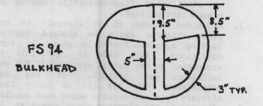
4. (Page 4-2) The location of the main wing at WL30 leaves only 1" on the FS94 bulkhead for the 3" tapes joining the wing to the bulkhead. The cutouts in the bulkhead should be lowered and angled to match the wing. (See drawing below.)
5. (Page 14-2) Don't mount the tailwheel until the engine is attached since the engine weight will deflect the canard and affect the tailwheel location.
6. (Page 9-6) If you plan to run a tube along the main wing shear web for strobe lights and antenna wires, you should make the cutout for the tube in the CS6 phenolic before drilling the seven 1/2" holes because they will conflict.
7. (Page 9-5) The following method for installing the main wing aileron slot cores and trailing edge cores was simpler than the plans: As has been suggested before, make only one set of aileron slot cores using the BL00 and BL50 cores. There will be a slight deviation from the proper 'twist, but it is within the accuracy that the cores can be installed anyway. Cut these cores to the length of the aileron plus 1.0". Remove the 'tails' on the slot cores. Finally, mount the cores at the proper location on the shear web. Remember to install the tube for strobe light wires if desired. Install the CS10, CS6 and CS7 attachments as shown in the plans, but do not put any BID cloth on CS10 or CS6. Put a flox corner where CS10 and CS6 meet the foam on the slot. Install the trailing edge cores with a flox corner where they meet CS10. Now sand and fill the foam to obtain a smooth flowing surface. The slot cores and trailing edge cores can now be glassed at the same time, draping the cloth onto the face of CS6 from each side.
8. (Page 9-5) Here is an alternative method for glassing the slots on the slot cores: Set the cores side-by-side on the table. Now place the ailerons onto the slots and five-minute the slot cores to the table and to each other. The cores are now straight, level and solidly mounted to the table. Attach 1" wide peel ply to the inside vertical surfaces of the slots with tacks spaced 4" apart behind the eventual trim line. Wetting the foam slightly with epoxy first will help hold the peel ply. Be sure that the peel ply does not extend below the vertical sides of the slots. Refer to how this was done for the ailerons in the plans. If you like, you can layup glass tapes onto Handi-Wrap and then transfer to the slot cores. This minimizes the amount of stippling required in the confined space inside the slots. This method really simplifies removing the 'tails' from the slots and the glass actually lays down nicer on the peel ply than on the foam. Be aware that the peel ply will cause the slot to be slightly narrower than without it, but my slots came out of hot wiring slightly too large anyway.
You can order a PDF or printed copy of QuickTalk #10 by using the Q-talk Back Issue Order Page.