Tri-Q Nose Gear Installation


- Details
- Category: TriQ Plans
- Published: Wednesday, 29 December 2010 09:17
- Written by Sott Swing
- Hits: 6853
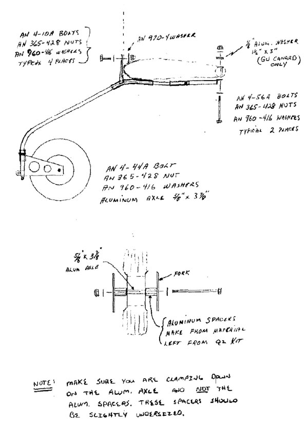
The nose gear assembly consists of the fork unit, main steelspring unit and the rear attach slip unit. Due to builder variationsand differences between the GU and LS canard, we use the rear attachslip piece to allow for these variations.
Prepare the aircraft for nose gear installation by removingany foam that might be present in an area 1" wide and centered onthe bottom of the canard. This will allow the gear to nest directlyagainst the canard bottom. A larger foam removal area must be madedirectly below the shear web (on the GU canard) or below the sparon the LS canard. This will allow the rear attach slip unit tobolt directly in front of the shear web on the GU or directly tothe spar on the LS canard. On the GU canard, this cut out areashould be enlarged to 3"x3" and, after sanding, a three bid lay-upapplied. The LS canard does not require any additional preparationas there are already numerous glass lay-ups in this area.
Now trial fit the gear into position with the slip unit inplace. With the nose tire installed and the fuselage position at22-1/4" firewall to floor and 28-1/4" split line to floor, thetire should just touch the floor. An aluminum spacer can be fabricatedand placed between the rear attach slip unit and the wing ifmore tire clearance is needed or the front firewall bracket can bedropped a maximum of 1/4" if less clearance is needed. If you dropthe front, an aluminum spacer block must be fabricated and placedbetween the gear and the wing so landing loads are spread to thewing and not on the four firewall attach bolts only. If the tireis within 1/4" either way, no further adjustments are necessary.
with the gear still in position mark the two rear attach holepositions. This should be within 1/4" and in front of the shearweb on the GU canard and centered on the spar of the LS canard.Drill through the wing using an 8" or longer 1/4" drill. Keepthe drill bit as vertical as possible so the exit holes on thetop side will look semi professional. Now fabricate a 1/8" aluminum"washer" about 1-1/2"x3" and place over the top through holes,mark and drill the 1/4" holes.
Bolt the rear slip unit into place and position the nose gearinto its approximate position. Level the fork using a good carpenter'slevel and place enough weight on the nose tire to firmlyimplant the gear against the firewall and bottom of the wing.Drill the 1/4" firewall attach holes one at a time and inserta 1/4" bolt to hold while drilling the remaining holes. Tightentwo of the bol ts and re-check everything.
Now mark the position of the rear attach slip unit on the steelgear. This is to establish a common reference for drilling the 1/4"holes through the slip unit. It isn't easy to achieve a good alignmentso take your time and make sure everything is in good positionbefore drilling the 1/4" holes.
Bolt the slip unit into place and then bolt the entire nosegear into position. Check for alignment and make sure there is nointerference between firewall bolts and any other parts of theengine. Adjust the fork fricti9n lock so there is about a 6 lb.force needed to move the tire when a horozontal force is appliedto the tire at the rearmost point. The friction will need to bechecked for the first ten hours or so to insure proper dampening.
You can now proceed with the fairing installation as previouslyoutlined.
|
NOTE:
|
We have not had the opportunity to install the gear in theQ200. Therefore, a careful check of the clearance betweenthe gear and oil sump is needed. In the event the drainshould interfere, the entire nose gear can be offset enoughto clear this drain. If a problem exists, call for assistance. | |