Q2 Plans Chapter 16 Page 16-04


- Details
- Category: Q-2/Q-200 Plans
- Published: Friday, 05 May 2006 20:05
- Written by Quickie Aircraft Corporation
- Hits: 3142
|
COWLING AIR INLETS
..... The cowling air inlets can now be cut into the cowling. They are nominally each 3.5" x 6.5" in size, with a 3/8" radius (using Bondo) around the 1 ip. A sketch is included for reference. 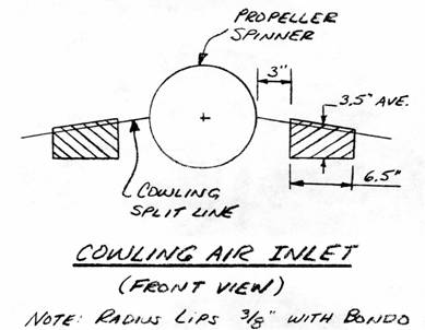 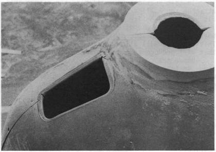 COWL FLAP CONSTRUCTION
..... In order to improve the efficiency of your Q2, we have utilized a simple cowl flap. .....Using a felt tipped marker, mark on the inside bottom cowling the 12" x 8.25" outline of the cowl flap. Trim 1.5" forward of the aft edge to remove the cross¬hatched area on the illustration. .....When the cowl flap is opened, it is necessary to have both sides closed off, like a dustpan. (See Section A-A). Flat laminated fiberglass (4 plies) is trimmed to fit the bottom cowl curvature and bonded to either side of the cowl flap with 2 BID. Allow room for the cowl flap to open up to 3.0" when making these side pieces. .....Carefully cut out the cowl flap from the lower cowling. Smooth up all rough edges. .....A short piece of the MS20257P4 hinge is used to hinge the cowl flap. It is located with 8 BSP42 rivets. To seal the remaining gap at the leading edge of the cowl flap, rivet asbestos along the width of the cowl flap with more BSP42 rivets, to form a secondary hinge and a primary air seal. The asbestos and the hinge should be located on the inside of the lower cowling. 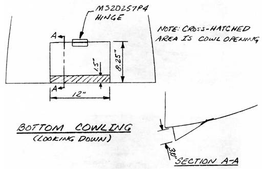 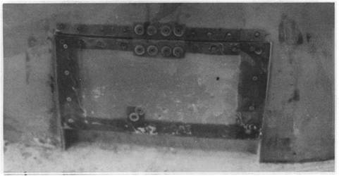 MOUNTING THE COWLING
..... The cowling is mounted permanently using K-I000-3 nutplates and AN507 1032-RI0 screws using an approximately 4" spacing. The nutplates are secured using AN426-3-5 rivets. Take time to accurately mount the cowling halves and you will be rewarded with"an excell ent fit. 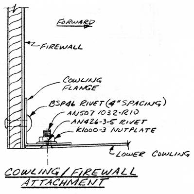 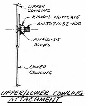 |
||||
|
||||
PAGE
16-4 |
||||