Q2 Plans Chapter 14 Page 14-10


- Details
- Category: Q-2/Q-200 Plans
- Published: Wednesday, 17 May 2006 15:05
- Written by Quickie Aircraft Corporation
- Hits: 3043
|
INSTALLING THE PITCH TRIM SYSTEM
..... The pitch trim system is a simple looking double spring system mounted in the center console forward of the control stick. It must be built exactly as per plans if you are to enjoy the same fine handling qualities as the prototype Q2. In addition to providing pitch trim capabilities, the system also serves to regulate the stick force per g of the control system in pitch. .....The illustrations are straightforward. The trim wheel is carved from plywood, and a dowell is bonded to it to allow the AN3-11A bolt to attach the trim wheel to the 0.375" O.D. x 0.049" wall 4130 Steel Tubing. A AN931-6-10 grommet is bonded to one of the TRl phenolic bearings (both of which are bonded to the vertical side pieces of the center console) in order to provide friction in the system. This is very important. Be sure to verify clearance between the pitch trim system and the CS13 rod and control stick. .....A hole is drilled-through the tubing to allow the 1/8" diameter nylon rope to be knotted twice for retention. Be careful to avoid kinks, and prewind the rope at least one turn around the tubing to avoid jerkiness in the pitch authority. Note that the #1 and #2 spring ropes wind in opposite directions on the tubing so that rolling the trim wheel forward yields a nose down trim direction. .....The rope should be replaced every 1 year/100 hours. See the "Initial Flight Testing of Your Q2" guide for information on altering trim rates and forces. 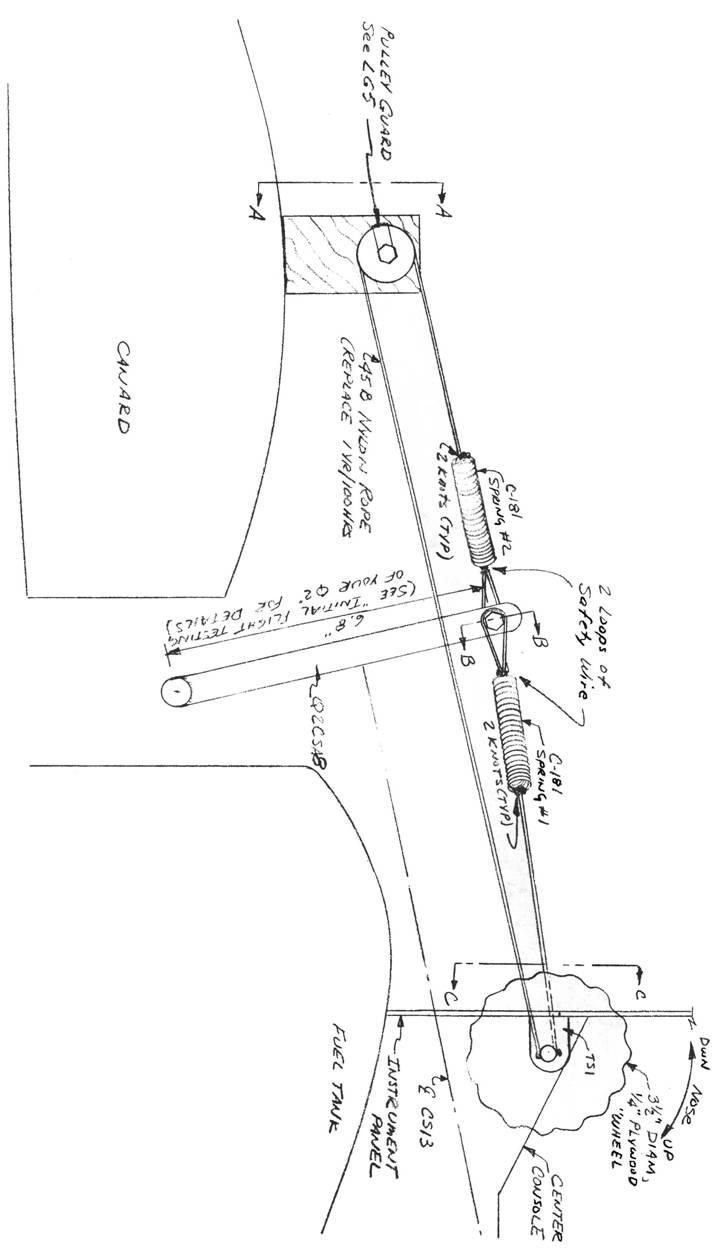 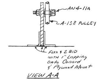 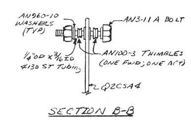 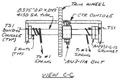 |
||||
PAGE
14-10 |
||||