Q-talk 92 - Dual Ignition for the Onan

- Details
- Category: Q-Talk Articles
- Published: Wednesday, 23 December 2009 16:24
- Written by Dennis Clark
- Hits: 3363
Dual Ignition for the Onan

Dennis Clark Newnan, GA
Dual Ignition Onan? Yes! It can be done! Why? What would you do if a plug wire falls off? What if the tachometer wire shorts to ground? (It happened to me.) Would you like to start that sucker a little easier and safer? Care for a smidgen more power?
I know, modern ignitions hardly ever fail, but with only two cylinders up front banging away, you're in more trouble if you lose one, compared with a four-cylinder engine. The latter might maintain your altitude?
Photo 1 shows the top of the cylinder head with the second spark plug installed. The original configuration allowed firing the plug at top dead center to avoid kick back during start-up. In a previous post, I thought that it might be a less than optimum location. While increasing revs, the engine would stumble with the second ignition only. I attributed this to possible excessive turbulence in this area. Later, after some experimentation, I found that the initial advance had to be 10 to 15 before TDC. This allows easy, no kick back, starting with no hesitation during throttle increase.
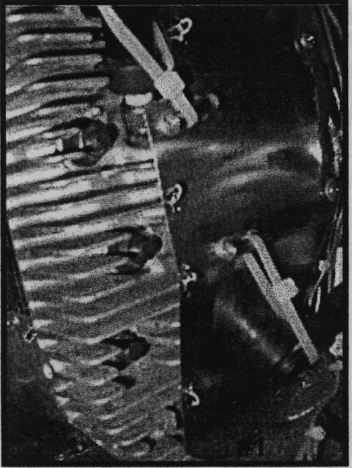
Photo 2 shows the connection to the original governor shaft. This is now used to control the ignition advance. (You have to find the governor parts that QAC threw away.) The arm can be made by bending a piece of metal around a #10 bolt and drilling a hole to fit the gov-shaft that is close but not touching the #10 bolt. Cut a slot to the gov.-shaft hole to give the #10 bolt a way to cinch down on the gov.-shaft. Drill a hole 1 1/4 "from the gov.-shaft hole for the advance cable. Grind off anything that does not look like the arm you want or if you used the QAC throttle set-up, you can use that arm, after direct routing of the throttle cable.
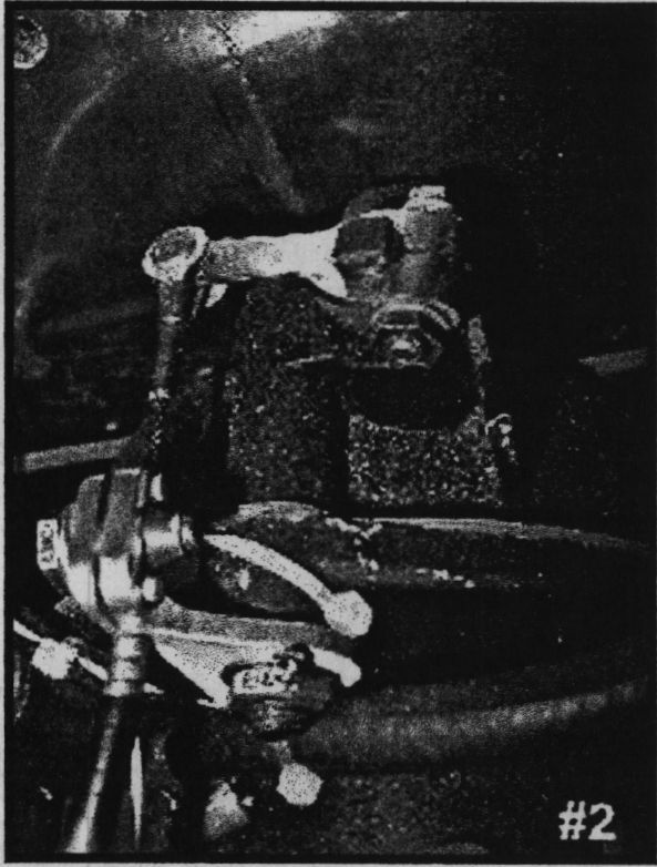
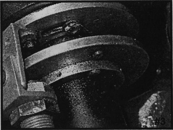
Photo 3 shows the advance mechanism at the crankshaft. Have a machinist fabricate three round plates of 1/4" aluminum. The first bolts to the front of the engine using the 4 #10 tapped holes around the crank. This plate has to be free to rotate 20 degrees or so. Your machinist will have to make these slots as large as the steel tubing used for spacers. Size spacers for the screws giving enough play to allow this slotted plate to rotate freely. I had to use valve grinding compound to "wear in" these parts for smooth operation. Be sure to clean well and lubricate before use. I used countersunk screws (heads on engine side of plate) to secure a 90-degree angle aluminum bracket. Use aircraft self-locking nuts here. (You always A/C grade fasteners, right?) From this bracket, hang your ignition pick-up. Mine is a MSD unit, so I had to add another bracket to mount it. The cable from the gov.-shaft is routed and attached to this plate to pull it clockwise as viewed from the prop looking toward to the flywheel. A spring is used to return the plate to the lesser advance at idle. Some experimentation with different springs may be needed. Full advance should be attained by 2500 RPM. I chose to limit the max advance to 30 degrees after looking at other engines that operate at about 3600 RPM.
The second plate is about the same diameter as the first with no slots. The center hole for this plate is slightly larger than the prop extension. (Did I mention that the prop extension has to be removed for this mod?) If it was installed with no corrosion preventative, you will have a hard time getting it off.
The final plate is actually a ring; it will be tapped for setscrews to secure it to the prop extension with rivets attaching it to second plate. On this second plate, the magnetic trigger is mounted. I drilled a press fit hole and pressed the magnet into it. Rotating this plate allows the timing to be set or changed.
Photo 4 shows the new spark plug hole inside of the cylinder head. I destroyed a set of heads by drilling and poking them to find what I considered to be the best location. The head in this picture and its mate are junk also. I had them "shaved" to provide increased compression. The machine shop cut them at an odd angle and had to buy me another set. This set had about 100 hrs. on them.
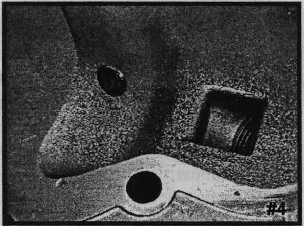
The hole for the plug is drilled to be at a 90-degree angle to the outside surface, if the fins were removed. I used a back spot facer to remove the fms down to the surface without cutting into the "meat" of the head. This area is just large enough to allow the 10 mm motorcycle plug to seat on the new flat surface. Then I used a larger back spot facer to remove more fins to allow a plug wrench to be used. This procedure minimizes the fin loss due to this mod.
Photo 5 shows the fixture that I used to drill at the correct angle. This fixture can be used on both heads. Two eye bolts and a little plywood and fiberglass will do the job. This fixture is used for the hole drilled for the spot facer shaft. Later, drill out the hole for the spark plug tap. Careful when tapping the plug hole, it is easy to get it started crooked. I used the drill bit sticking out the other side of the hole to get a better idea of the angle to start the tap.
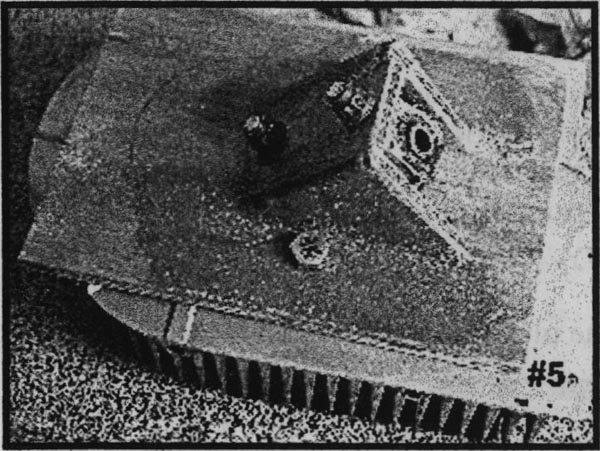
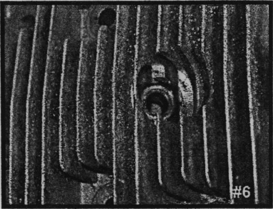
Photo 6 shows the fins of the modified head. If you look closely you can see the step of the fins.
The plug wire falling off? It didn't happen to me, but I read about it happening to someone else.
Tach wire shorting to ground? It did happen to me. During pre-flight, the original system was dead. The beautiful thing was, the previous flight was safely concluded.
Start easier? The little Onan had not been run for over a week. The temperature was 39 degrees. The local CFI was trying to start a spam can for a flight. Mr. Onan started on the third blade. I flew for an hour and a half. While I was tying down, the CFI was still trying to start his bird.
More power? Not a huge amount but at cruise when I shut down the new electronic system with its 30 degree advance, and run on the original ignition with the fixed 21 degree advance, I do experience a drop in RPM.
Other things: While trying to reduce weight, I looked at the MSD ignition box, big and heavy. Perusing a J.C. Whitney catalog, I saw the Pertronix electronic ignition system for VW engines. It fits inside of the distributor. I haven't bought it yet but it might save a pound or two.
I use the 10mm NGK X8HSA spark plugs. One flier told me that Onan heads crack in the area that I chose to put the new plugs. That's just a heads up. Mine show no evidence of cracking yet.
You can order a printed copy of Q-talk #92 by using the Q-talk Back Issue Order Page.