Q-talk 145 - Better Q1 Fuselage Split Plans


- Details
- Category: Q-Talk Articles
- Published: Thursday, 24 February 2011 11:12
- Written by Leon McAtee
- Hits: 5512
by Leon McAtee
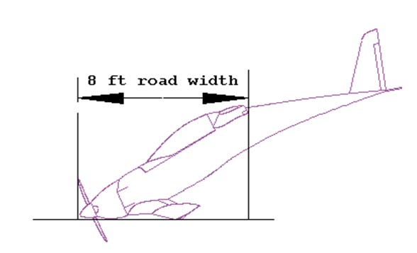
The split fuselage option is one that QAC came up with after the Quickie had been in service for some time. It’s original purpose was to facilitate transportation on US highways at a legal 8 foot width. The split fuselage option has other added benefits. Once the fuselage has been cut the tail portion can be stored in a vertical position freeing up considerable floor area in small workshops making construction much easier. Also the easy removal of the tail section makes future inspection and repairs a far simpler task.
Overview
QAC never specified exactly where the cut was to be made so the exact location is up to the individual builder. The general procedure is to lift the tail up until the nose is almost touching the ground. This is needed to reduce the horizontal distance between the nose and the trailing edge of the main wing to less than US legal road width of 8 feet. Once the angle needed to obtain this distance is determined a cut line is drawn on the fuselage perpendicular to the floor. External reinforcing glass layers are added, the fuselage and external reinforcements are cut, the interior surface is contoured and reinforced for the attachment plates, the attachment plates are fabricated and installed, and the fuselage is bolted back together. Any internal connections such as the rudder cables, antenna cables, electrical wires, pitot static lines, etceteras, also need to have some kind of connection to allow quick separation.
Procedure
As noted above the first thing to do is raise the tail and mark the split line. A permanent marker used to make several small dots is a good starting point. Once you have tentatively established the split line double check to make sure that the cut will not damage any internal structure. The bottom cut should not be forward of FS 89 and should probably be 3” (76mm) aft of FS 89, or at FS 91. The top cut should not interfere with the aileron torque tubes or phenolic bearings. Unless you plan to remove the ailerons to meet the legal width there really is no reason to cut any further forward than the trailing edge of the ailerons.
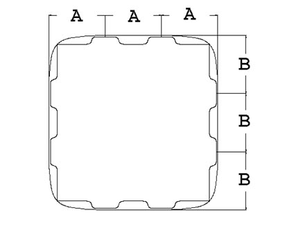
Adjust your split line as needed and then connect the dots. A quick and easy way to make nice straight lines on curved surfaces, such as the Quickie fuselage, is to use 2 inch (50mm) wide masking tape to connect the dots. While you have the permanent marker in hand locate the position of the 8 attachment tabs and mark these locations on the fuselage. The attachment tabs are located so that each surface of the fuselage, top bottom, left, right, are divided into 3 equal lengths. See the diagram below for clarification.
 |
| Once the split line has been well marked sand the exterior surface dull for good secondary bonds at least 3 inches fore and aft of the split line. Then lay one 6 inch wide layer of BID(45) centered on the split line. Lay on a second 3 inch wide BID(45) on top of the first, also centered on the split line. Use 20-minute structural epoxy or fast hardener so you don’t have to wait too long for the lay-up to dry. Once cured use a hack saw or other suitable tool to cut the fuselage along the split line, which you should be able to see through the 2 reinforcing layers. |
Mark a line around the inside of both the for and aft fuselage portion 1.6” (41mm) past the split line and another line.
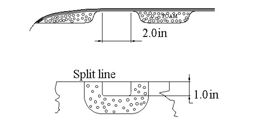
At each attachment tab location remove a 3” X 1.6” (76mmX41mm) square of the original glass, with rounded corners, and then remove a 2” X 1” (50mmX25mm) piece of foam. Sand the inner surface of the outside glass for a secondary bond and taper the exposed foam for a smooth glass transition. Sand the entire inner surface of the fore and aft fuselage sections at least 2.6 (66mm) inches past the split line for a secondary bond. See the drawing below for clarification.
Lay 9 plies of 1”X 2” (25mmx50mm) BID(45) on the inner surface of the exterior glass at each of the 16 mounting tab cutouts. Next lay 2 plies 2.6 inch wide BID(45) strip around the entire inner perimeter of the split line of both fuselage sections.
To make the split line more durable you may wish to dig out the foam between the inner and outer fuselage glass layers between the 8 mounting tabs to a depth of around ¼” to 3/8” and fill this void with a flox/micro mixture. If you do this to the forward section only, and sand the surface flat before drilling the attachment tabs, as outlined below, you can make an almost perfectly matched split line. Once the rear section has been installed and drilled to match the mounting tabs you can then dig out the foam as you did with the forward section and fill this with the flox/micro mix. Another option is to combine this step with the installation of the FC-1’s. This does require a bit more planning and the extra time required may tend to rush those that are not quick with their composite work. Cover the mounting tabs and forward fuselage section with good mold release and bolt the fuselage together before the flox/micro hardens. This gives you an almost invisible parting line. You can do this matching before or after the exterior of the fuselage halves have been surface finished. I have better results when I do the exterior finishing before adding the flox/micro to the second fuselage section.
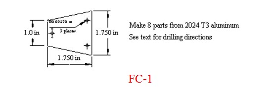
If you haven’t already made the 8 FC-1’s do so now while the glass is curing. Using a 0.125” drill bit drill only the 2 holes for the forward AN525-10R10 screws. Make a ninth FC-1 to use as a drill jig. Drill the 2 forward holes to the final size, and the third, rear hole, to 0.094” in this one piece. Mark each of the 8 FC-1’s along it’s center line. This line is then used to align The FC-1’s with the split line.
Clamp each tab to the forward section of the fuselage using the center line and drill from the inside out with the final size drill. Install the 16 forward attachment screws, with no washers from the inside out and tighten the nuts so that the FC-1 tabs are free to flop back and forth about .125”. Jig the rear half of the fuselage in place. Use tape, Bondo?, rubber bands, or what ever is handy, to secure the aft portion. Using the ninth tab that you made for a jig, place it on the exposed ends of the improperly installed AN525 screws, on the forward section, and using the rear hole in the jig tab for location, drill the rear hole with a 0.094” (3/32”) drill bit. Drill into the rear fuselage glass and then slowly drill through the FC-1 mounting tab. A sharp drill really helps at this point to reduce the pressure needed to drill the tab.
Mark the FC-1’s so that they can be reinstalled in their original positions. Remove the rear fuselage section and all of the FC-1’s. Apply mold release to the aft half of the FC-1’s and then mix up a small batch of flox. Use 20 minute structural epoxy if you think you can accomplish the next steps in that amount of time. If not use fast hardener. Apply a small dab on each of the 16 mounting surfaces, after a light sanding of the glass surface. Bolt the tabs in place on the front section using the AN525 screws, but this time install them properly. If you have some old Clecoes use them. Install the rear section a second time and either bolt the tabs in place or use the Clecoes. In either case mold release should be used so they can be removed. If you are doing this before the main wing has been installed simply reach in and tighten the bolts. If you are doing this with the main wing already installed you will probably need to use a helper or a some creativity to get the bolts tight. (This is the reason why using some old old Clecoes is suggested.)
Once the flox has cured remove the 3/32” bolts or Clecoes from the aft fuselage section one at a time and drill to final size for the AN525 screws. Remove the aft section and then install the K1000-3 anchor nuts on the FC-1’s. Leave the FC-1’s glued to the front section oof the fuselage while doing this. There should be no reason to remove the FC-1’s from the front fuselage section unless repair is needed. You should now have a snug rattle free fuselage split line with bolts that line up perfectly with their holes.
Some have substituted AN509 (MS24695) countersunk screws and NAS390B10P flush countersunk washers for reinforcement. Also a slight inward bend on the aft portion of the FC-1’s and a slight taper on the mounting tab glass surface can make installation much easier.
You can now go back and dig out the foam between the glass layers in the aft fuselage section and fill with flox/micro as described above, if you so desire, and did not complete this step during the installation of the FC’1’s.
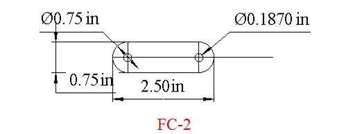
Make up 2 rudder cable attach tabs, FC-2 from .063 2024T3 aluminum strap and install in the rudder cables using 4) AN115-6 cable shackles, 4) AN10-4 thimbles, 4) AN3-5A bolts, and 4) AN364 elastic stop nuts, to make them easily detachable.
 |
| I would prefer to see AN3-5 (drilled shank) bolts used with MS 17825 elastic castle nuts – AND – safety wire/cotter keys on a primary control hookup that is intended for routine use. This combination is a double safety in that if you forget the safety wire the self-locking feature of the MS 17825 is still functional and the safety wire is a good backup for a lock nut that may have lost it’s “grip” over time, or through repeated use. |
Make the right and left cables different lengths to reduce, or eliminate, the possibility of getting them hooked up backwards. It is also a good idea to get in the habit of disconnecting the cables from different ends of the FC-2’s. Each time you re-rig the aircraft do a positive control check just to make sure the rudder works the correct way. Make sure that the connections will not interfere with the FS89 or FS110 bulkheads, or hang up in any other manner.
Because of the almost infinite number of different connections that may also be needed to attach the aft section of the fuselage, depending on what options/modifications have been installed, it is left up to the builder to design a simple yet fool proof method of attachment.
[EDITOR'S NOTE: Leon also provided an original set of QAC Fuselage Cut Plans in PDF format. I cleaned up the pages to remove smudges and the binder holes. You can download these by clicking here.
By comparing the PDF with the text above you'll notice immediately that Leon has filled in many gaps left in the original QAC plans. We appreciate your hard work Leon! Thanks a million!]