- Details
-
Category: Quickie Plans
-
Published: Monday, 12 May 2008 10:28
-
Written by Dan Yager
-
Hits: 2112
FUEL CAP
The fuel cap is made from a top off of a 1 pint storage bottle. This is because the plastic will bond good to the composite fuel tank.
If you don’t mind occasionally spilling fuel inside the cockpit, and if your FAA inspector permits, you may elect to mount the cap directly to the tank inside the fuselage. However, we feel that it is worth the extra trouble to make a filler pipe and mount the cap on the fuselage side where it is accessible only from the outside. By the way, if you elect to use the inside fuel cap idea, you will have to plumb a separate fuel tank vent line;otherwise, a small hole in the cap will vent the vapors to the outside air if the cap is mounted on the fuselage side.
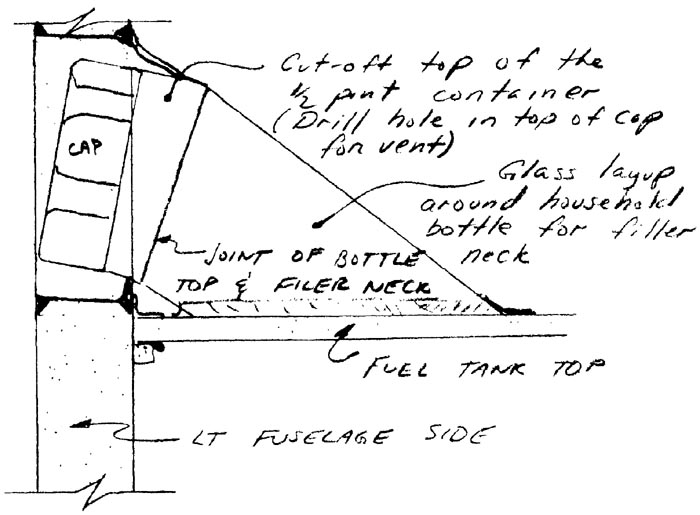
Begin by cutting the storage bottle at the neck (right before it widens out). Next, for a filler neck mold, find a household bottle with a compatible diameter. After placing some Saram Wrap around the bottle, lay up 3 plies of BID around the bottle and allow to cure. Then trim it (after removing the bottle, of course).
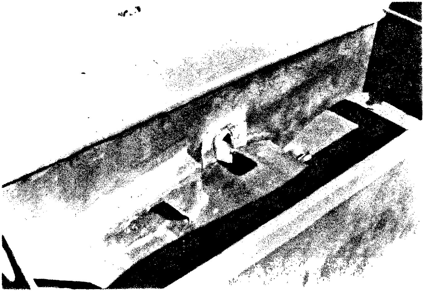
The pictures included in this section show you what the finished product looks like. Basically, you must cut a hole in the fuselage side, and angle the filler neck and cap so that it will stay as low as possible to avoid taking up space occupied by the side console and left hand instrument stack. The fuel cap is mounted on the left fuselage side.
The hole through the fuselage side is protected by using a micro corner inside and out, and a BID layup around the hole to protect the bare foam.
Later on, you may wish to fabricate a light metal cover for the hole.
Use two plies of BID to join the filler neck to the tank and the cap to the filler neck. Work carefully to avoid leaks which might allow fuel vapors into the cockpit.
FUEL SYSTEM PLUMBING
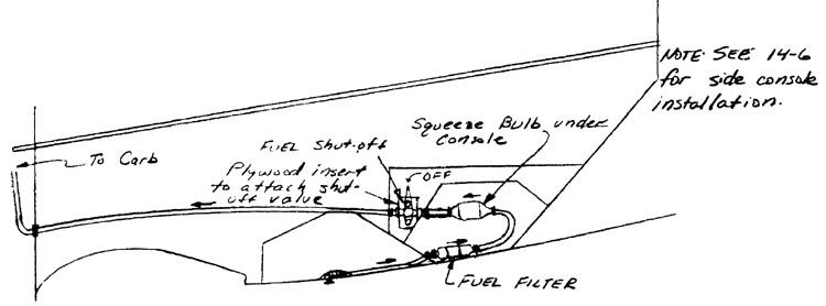
The fuel filter and squeeze bulb are located as shown. Make sure that you look at the parts and get the fuel flow going in the proper direction. Hose clamps are used to connect the 3/8’ diam. Nylo-Seal tubing to the parts.
The fuel shut-off valve is located on the left side console with the handle sticking through into the cockpit area so that it can be actuated in flight. We suggest that the handle be clocked so that the fuel valve is OFF when the handle is vertical. That way, you will be less likely to take off with it in the OFF position. If the handle protrudes too far into the cockpit area, you may want to use spacers behind the bolts. The valve bolts to a plywood insert.
Sit in the cockpit (you probably have already been sleeping in it), and verify that you can reach the squeeze bulb and the fuel shut-off valve in flight. If not, relocate them to where you can.
The Nylo-Seal tubing is also used to run the fuel up to the carb from the fuel shut off valve. An AN931-6-l0 grommet is used at the firewall where the tube goes through.
Use hose clamps to secure the fuel line connections.
