Login Form

Q1 Plans Chapter 11 Page 11-7

BRAKE INSTALLATION

The brake system consists of one mechanical tire scrubber per tire (BSW1), actuated by a 1/16” cable that runs over a pulley (AN210-1A) in the wheel pant, through the 3/l6" diameter Nylaflow tubing to the opposite wheel pant where it connects up to another BSW1 in the same fashion. The system is actuated by a pull handle in the cockpit. The brake shoes (BSW1) are spring loaded in the ‘off” position.
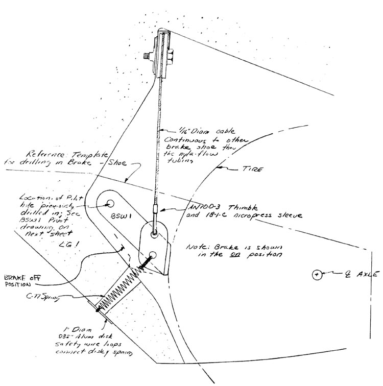
Quickie Brake Installation

CONTINUED ON NEXT SHEET

Q1 Plans Chapter 11 Page 11-8

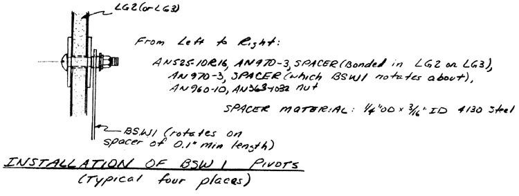
Quickie BSW1 Installation

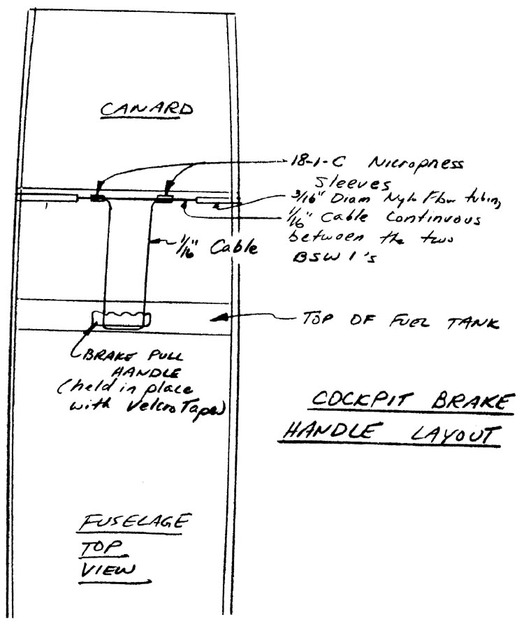
The brake pull handle is carved out of pine, or any other durable wood. The 1/16” cable is looped through a hole in each end of the handle and then is connected with two nicropress sleeves to the 1/16” brake cable that runs continuously from the left pant to the right pant. Remember to thread the two nicropress sleeves for the brake handle cable before hooking up the two BSW1’s.

The brake pull handle is positioned conveniently on top of the fuel tank with Velcro tape.

After installation, check that the brakes do not drag against the tire in the “off” position.

Also, brake efficiency will be poor until the shoes and tires have worn in somewhat.

Quickie Brake Handle Installation

CONTINUED ON NEXT SHEET