Q1 Plans Chapter 11 Page 11-3
- Details
- Category: Quickie Plans
- Published: Friday, 29 August 2008 01:00
- Written by Dan Yager
- Hits: 1984


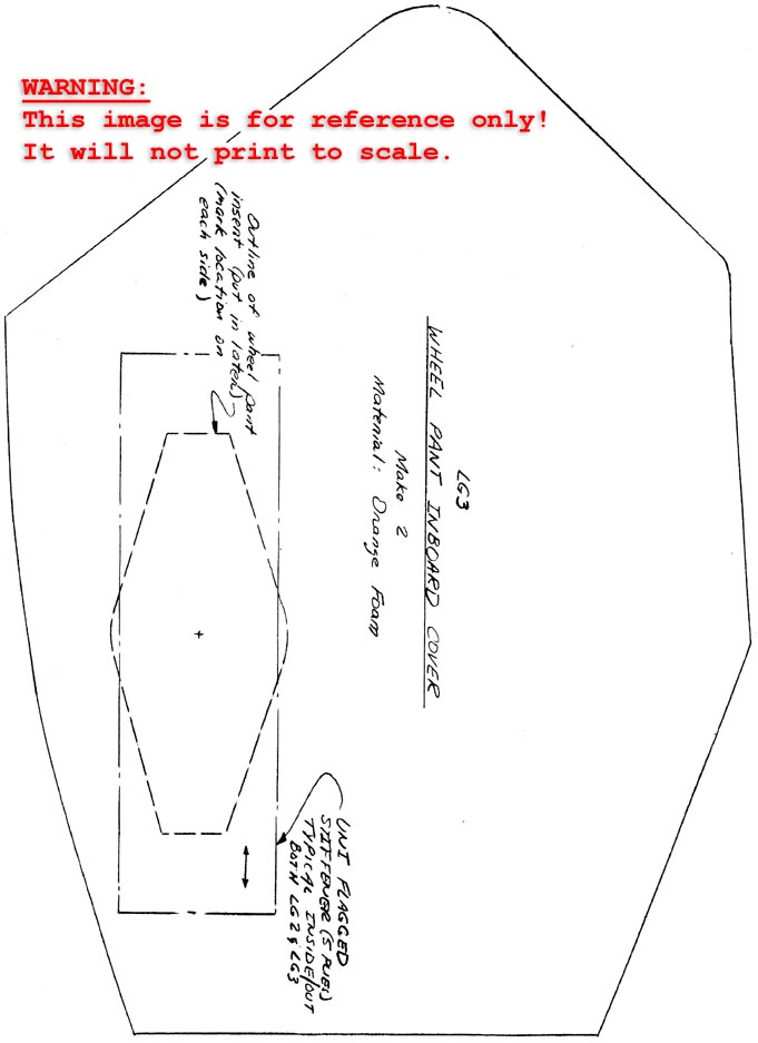
Next, you will need to join LG1 and LG3 with micro. Remember that the LG3 goes on the inboard face of LG1(i.e. as you visualize the wheel pant mounted on the canard, LG3 is on the same side of the LG1 as the fuselage is). Leading edge and trailing edge marks have been included on the LG1 sketch to allow you to line up the pieces; basically, LG3 covers up the LG1 cutout, You may need to use some weight to hold the pieces together until they have cured.
Once that curing is acc.om,dished, lay the combination on the table with LG3 face down, and layup two plies of BID on the inside of LG3, allowing the cloth to lap up on the LG1 faces that surround LG3.

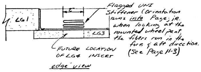
Now, you are ready to flag the UNI stiffener over the location of the LG4 inserts. Begin with a piece of UNI cloth 10” x7” with the orientation along the 7” edge. Flag the piece 5 times along the 7” edge (ie. every 2”). Flagging consists of the following procedure:

While the layup is curing, take LG2 and layup two BID on the inside face (i.e. the face that will be inside the LG1 cutout when it is attached. Roughly trim the glass so that it doesn’t extend beyond the edges of LG2, but don’t be concerned if you trim somewhat inside the edges. Flag a UNI stiffener to LG2 just like you did with LG3, remembering that the stiffener is on the side of LG2 that will be inside the LG1 cutout when LG2 is joined to LG1.
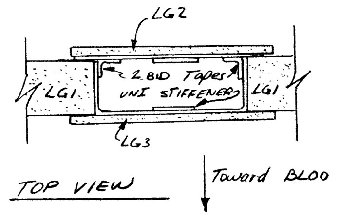
While the LG2 layup is still tacky, join LG2 to LG1 with micro. Now, layup two BID tapes on the inside to join the LG2 glass layup to the LG1 glass.
At this point, you should have a sandwich, with LG1 as the core, LG2 as the outboard face, and LG3 as the inboard face.
Drill in the pulley hole with a short angle drill. If you don’t have one, cut the hole with a small exacto knife.

Next, the two LG4 inserts must be placed into postition after the previous layups have cured. Remove orange foam from LG2 and LG3 down to the inside glass layup in the areas on the L02 and LG3 patterns which denote the locations of the LG4 inserts. Then use micro to permanently insert the LG4 inserts.
After these layups are cured, drill in the pilot holes for the axle with a long 1/4” drill. To do this, with the wheel pant laying flat on the table, drill through both faces, keeping the drill perpindicular to the pant.
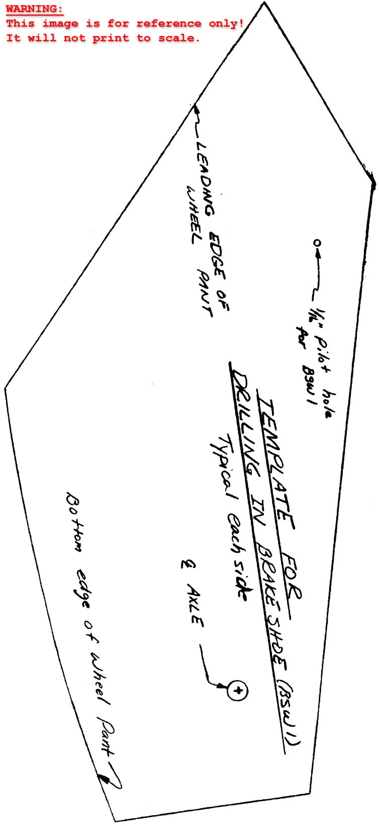
The next step is to drill in the .1/16” diameter pilot holes for the brake assetnbly(BSWI). Use the template provided and carefully line it up with the edges of the wheel pant and the axle hole you just drilled. The pilot hole should be drilled on each side of the pant.

CONTINUED ON NEXT SHEET