Q1 Plans Chapter 10 Page 10-12
- Details
- Category: Quickie Plans
- Published: Saturday, 06 September 2008 01:00
- Written by Dan Yager
- Hits: 2348
RIGGING THE ELEVATOR SYSTEM
In this section, you will drill in the AN3-14A (2) and AN3-11A bolts joining CSA7 to CSM1, CSA8 to CSM1, and CSA6 to CSA8. Before drilling any of these bolts in, you must make sure that proper elevator travel is available.
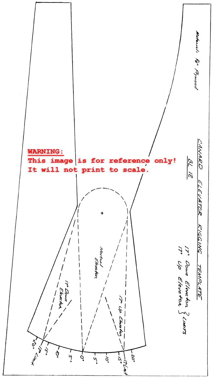
Make the Elevator Rigging Template. Mount the elevators onto the canard, and set the elevator rigging template in place. Tape the elevator at 0 deg.
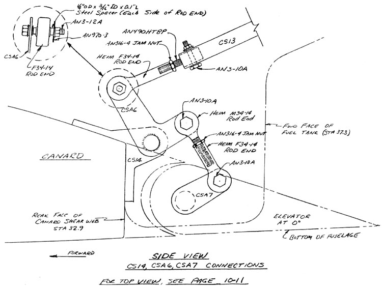
Begin by connecting CSA6 and CSA7 together with the Heim M34-14 and F34-14 rod ends. Notice that the arms on CSA6 and CSA7 must be parallel. You accomplish this by adjusting the length of the rod-end combination.
The elevator must travel 17 deg. up before stopping. The drawing shows the proper orientation of the arms at an elevator position of 0 deg. (about 30 deg. from the horizontal). Before drilling in the AN3-l4A bolt in CSA7, verify that the assembly can go 17 deg. up or down without restriction, or binding. If there is a restriction, it will probably be CSA6 hitting the canard in the 17 deg up elevator direction. When you are sure that the right elevator has the proper travel up and down, drill in the AN3-14A bolt that joins CSA7 to CSM1.
Next, with the left elevator at 0 deg., set CSA8 so that its trim arm is vertical. Now you can drill in the AN3-14A bolt that connects CSA8 to CSM1.
Finally, with both elevators at 0 deg., drill in the AN3-11A bolt that connects CSA6 to CSA8.
Now do a final check of the elevator system to verify that the elevator will travel 17 deg. up and down without bind ing or interference.


