Q1 Plans Chapter 9 Page 9-6
- Details
- Category: Quickie Plans
- Published: Friday, 26 September 2008 01:00
- Written by Dan Yager
- Hits: 2502
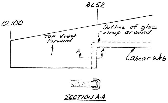
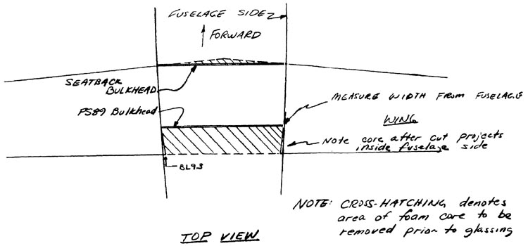
Construction begins by glassing the aileron slots on both inboard pieces. When the layups are cured, cut the BL52 and BLOO templates at the 18-A-B-C-18 line. Use these templates to hot wire the inboard foam cores into two pieces each in preparation for laying in the shear web.

Before doing that, however, the wing must be jigged upside down on the layout table.
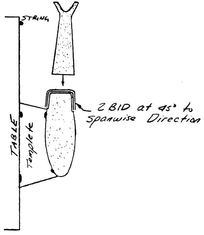
Make some wood templates roughly cut to represent female versions of the top portions of the hot wire templates. Full size drawings for these are included. These templates are used to jig the wing cores with the correct dihedral.
To help in getting the trailing edge of the main wing straight(i.e. perpindicular to BL00), the following procedure has been developed:
- Run a taut string from one end of the table to the other. To get it taut, you may want to let it extend over the side of the table and hang weights from it. Its location should be at the aft end of the BL100 female jigging template.
- Study the full size female jigging templates for BL100, BL52, and BLOO. Notice that a deminsion is given from the string to the aft edge of each female jigging template; e.g. the distance is 0” for BL100 because you set it that way.
- By using the distance given, you can set the inboard female jigging templates to give a straight trailing edge when the foam cores are placed in position.
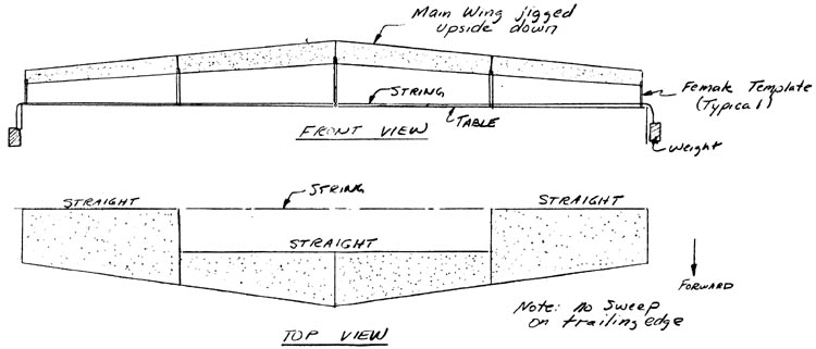
As you are locating the cores in position, check to verify that the level lines on the cores are level. This is important so be careful.
At BL00, you will have to bevel the two inboard wing foam cores to allow them to fit together flush at the proper dihedral angle.
Also, stand back and cight spanwise along the wing to verify that the wing is not bowed or kinked. A straight edge laid spanwise is also useful for this.
Don’t be concerned if the templates need to be moved inboard or outboard - slightly to remove any bows or kinks. When everything is satisfactory, mix up some bondo and bondo the templates to the table top in the proper locations. After that is accomplished, the foam cores should be just resting on the templates.
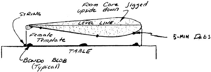
The next step is to join the foam cores together with micro slurry. Check each level line as you do this. Before stopping, 5-.MIN the foam cores to the templates with small dabs and being careful not to move the cores.
CAUTION! The foam cores must fit within 1/16”, and the slow epoxy must be used to join them, or exotherm damage will result.
CONTINUED ON NEXT PAGE


