Q1 Plans Chapter 12 Page 12-1
- Details
- Category: Quickie Plans
- Published: Friday, 29 August 2008 01:00
- Written by Dan Yager
- Hits: 2263
FUEL TANK INSTALLATION
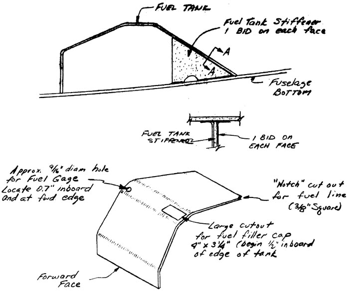
Begin by cutting the openings for the fuel gauge and filler cap assembly, and the notch for the fuel line.
Next, fabricate the fuel tank stiffener from orange foam. The semicircle in it is to allow fuel to drain from one side to the other. Once you have the approximate shape, join it to the fuel tank with one BID on each side.

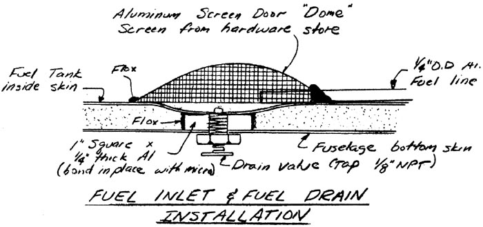
Now, you are ready to install the fuel inlet line and fuel drain. The fuel drain is threaded into the 1/4” thick aluminum plate you installed prior to glassing the outside of the fuselage. The screen is used to encompass the fuel inlet to keep out FOD. It is dome shaped and held in place with Flox. The fuel inlet line is 1/4” diameter Aluminum tubing. Use lots of flox where the tubing meets the screen. The line is run to the left rear part of the tank at the fuselage side, so that it can exit the tank at the notch you previously made in the fuel tank.

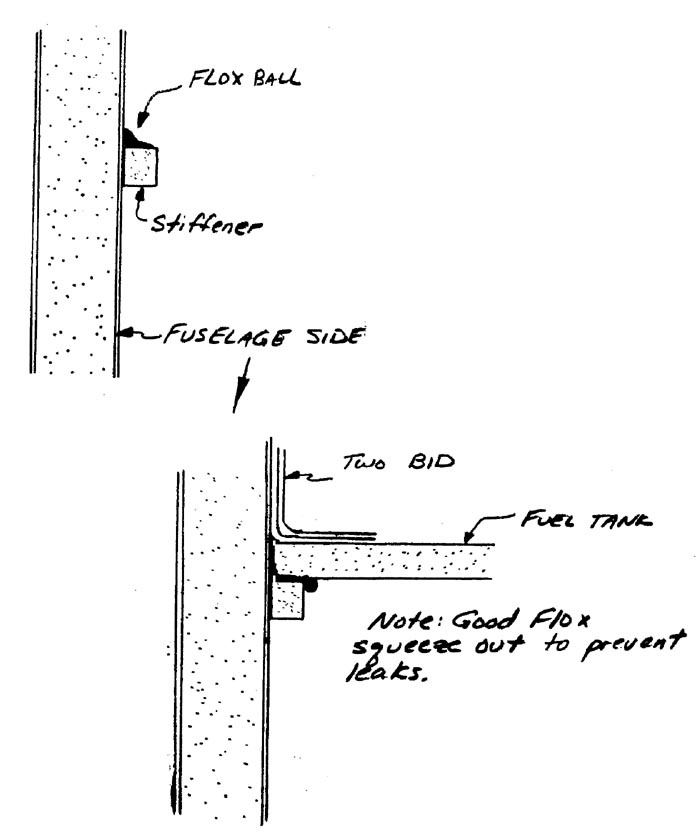
In order to provide a good leak- proof seal around the fuel tank after installation, small stiffeners are placed along the fuselage side so that upon installation, the fuel tank will sit down on them, thus assuring good squeeze out of the flox. These stiffeners are nominally .3” x .3”. They are located in place by dry fitting the fuel tank in place, tracing around the fuel tank on the fuselage side, removing the fuel tank, lowering the traced lines about .3” to allow for the fuel tank thickness, and then installing stiffeners with flox. Let the stiffeners cure before installing tank.


