- Details
-
Category: Quickie Plans
-
Published: Friday, 17 October 2008 01:00
-
Written by Dan Yager
-
Hits: 3681
FUSELAGE BOTTOM
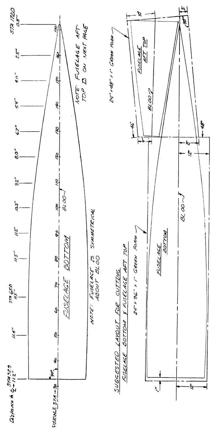
Initial Layout - Join together two pieces of green foam as shown. Locate and mark BL00 on the foam with a felt- tipped marker. Do not be afraid to gouge the foam to a depth of about 0.2” in order for the line to remain visible. Mark STA32.9 about 1” from the left edge of the first foam piece. Now, using STA32.9 as a reference, mark and label stations every 10 inches starting with STA4O (e.g. STA4O, STA5O, STA6O, etc.).
The next step is to layout the fuselage bottom using the given offsets. As an example, at STA5O, draw a line perpendicular to BL00. Measure along that line 11.4” from BL00 and place a mark. That mark defines the outside edge of the fuselage bottom at STA50. This procedure should be repeated for each STA/Offset listed.
Then, using a long, flexible straight edge, fair a smooth curve thru all of the points. Since the fuselage bottom is symmetrical about BL00, this procedure can be repeated for the other edge.
A similar technique may be used to layout the FUSELAGE AFT TOP.
Finally, using a butcher knife, carefully cut out both the FUSELAGE BOTTOM and the FUSELAGE AFT TOP.
CONTINUED ON NEXT PAGE


