Q1 Plans Chapter 10 Page 10-6
- Details
- Category: Quickie Plans
- Published: Friday, 12 September 2008 01:00
- Written by Dan Yager
- Hits: 2424
LAYING UP THE BOTTOM SKIN AND SPAR CAPS
Using a hard block on the foaia cores, clean up all joggles, excess micro, and bumps. At BL10, left and right, round the joints so that the glass can flow smoothly across BL10.
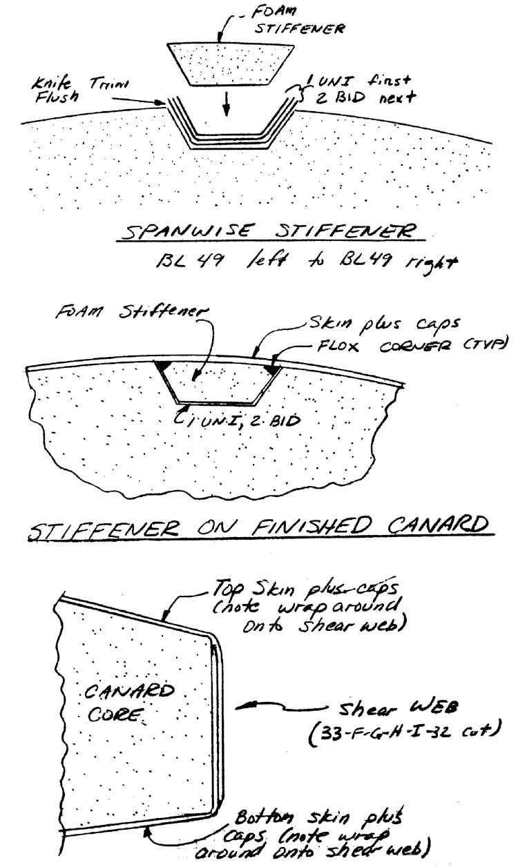
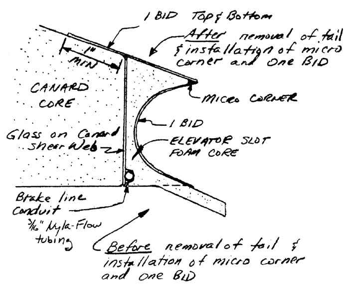
Round the aft face of the shear web slightly so that the glass will turn the corner ok.
You are now ready to lay up the bottom skin and spar caps. This layup will require about 3 hours and take at least 2 individuals, and preferably 3.
The procedure used is identical to that used on the main wing. Begin by measuring, and then cutting the UNI cloth for the skin. As before, roll the cloth along the cut direction and mark it with the width. Remember that the UNI plies are crossed at 45 deg. to the trailing edge of the canard to provide torsional stiffness. The fibers must be straight, so take your time getting the wrinkles and kinks out. Unrolling the cloth as you need it is advised also to reduce the awkwardness. Use scrap UNI oriented in the same directions to fill any spots not covered by the main skins.
At the leading edge, let the cloth hang down vertically,. Trim to within 1” of the tangent point. Trim the rest of the edges to within 1” also. At the trailing edge(the shear web) the UNI must wrap around down to the bottom of the face.
No overlap is required; just butt fit the skins together. Squeege the cloth well to avoid the buildup of excess resin.
Find the canard spar caps A, B, C and D. These will be put on in that order. Use the technique used on the main wing to put them on. In order to reduce the buildup of material on the canard shear web, trim B and D even with the trailing edge so that only A and C wrap around down to the bottom of the shear web.
Peel ply the joints, the entire shear web, and the initial 2” of the leading edge.
Knife trim the leading edge at the tangent point before quitting.
Let this bottom skin cure for at least one day.
LAYING UP THE TOP SKIN & SPAR CAPS
Build a framework out of lumber and bondo to hold the canard jigged in place while you turn it over.
After the canard has been turned over, leave the lumber on and check the level of the tips. Shim as necessary to get the tips level; then bondo the jigging to the table in preparation for glassing the top skin.
Lay in a f lox corner at both BL1O left and right, just like you did on the bottom of the canard.
Clean up all joggles, excess micro, and bumps. At the leading edge, feather the bottom skin to a feather edge at the tangent point. Remember that the top skin must wrap around the leading edge such that it overlaps the bottom skin by about 2”.
Before glassing the skin and spar caps, however, you will have to complete the spanwise stiffener. To do this, lay in the one UNI(with the fibers running in the spanwise direction), the two BID (with the fibers at 45 deg to the span- wise direction), and the foam stiffener. Hold the stiffener down with nails through the stiffener into the canard foam core. Knife trim the excess glass and sand the area smooth so that it blends in nicely with the canard core.
Although the layup involves more spar caps than the bottom, you should still be able to finish it in about 3 hours with two or three people.
As before,trim every other spar cap at the trailing edge (i.e. let E, G, I, and K wrap around).
Knife trim the glass at the tips and leave the canard tips square.
Permit the canard to set for two days before breaking the lumber loose. Before doing that, bondo a board onto the wing in the level position so that you will be able to easily tell when the canard is level as you mount it later to the fuselage.


