Login Form

Q1 Plans Chapter 9 Page 9-10

MOUNTING THE OUTBOARD AILERON PIVOT

The outboard pivot is mounted at approximately BL38.

Screw CSM3 into CSM2 and retain it with a locknut, as sho\ün. It must be tight. Round the end of CSM3 slightly.

Measure 28” outboard from the in board end of the aileron(that’s the end which still has CS9 visible). Using a router bit, route a slot 1/8” wide for about plus or minus 25 deg. of rotation. (see sketch). Next, insert CSM2 into CS9 with the flange pointing inboard You may have to sand CSM2 to get a snug .f it. Push CSM2 outboard thru the tube with a stick until you just see it flush with the routed slot. Rivet 3 MSP43 cherry rivets to hold it in place.
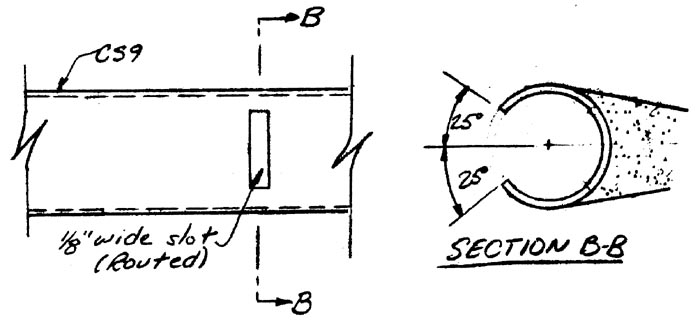

Mounting the Outboard Elevator Pivot

The routed slot must be opened up so that CS11 can slide off of CSM3 and out of CS9 while remaining perpindicular to CS9. This means that the slot must be about 0.5” to 0.6” wide. Also, check to see that CS11 can rotate about CSM3 approximately 25 deg. in each direction while inside CS9. Debur the slot and round all corners to avoid stress cracks. Do not make the slot any larger than you have to.

Repeat this procedure with the other aileron. Be careful that the flange on CSM2 points inboard so that CS11 will slide off CSM3 as the aileron is moved inboard

CS1O is a shaped block of red foam which is mounted in the wing. Later on, CS11 will be mounted in CS1O permanently. To find out where CS1O should go, tempor arily set each aileron in its approximate position on the wing, with the inboard aileron edge at EL1O. CS1I should be against CSM2. Now you can mark where CS1O must go to capture CSI1. Remember that to remove the ailerons, they are moved inboard(while CS11 remains fixed in CS1O) until CSI1 slides off CSM3; then the aileron can be pulled off. If you don’t stand back and think about this, you are likely to error during the installation.

Once you know where CS1O goes, remove the blue foam of the wing core and install CS1O with dry micro, and sand to remove bumps and joggles. CS11 will be per manently installed into CS1O later during the aileron installation and rigging.

One BID over CS 10, top and bottom is used to permanently attach CSIO to the main wing
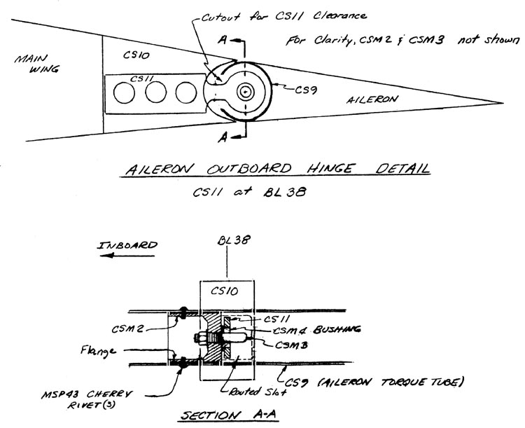

Mounting the Outboard Elevator Pivot

Q1 Plans Chapter 9 Page 9-11

INSTALLING THE AILERONS

The ailerons are installed and rigged prior to the wing being mated to the fuselage. Therefore, after mating, only CS5 and CS12 need to be hooked up for the aileron system to function.

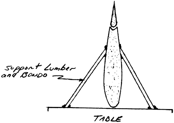
Begin by jigging the main wing vertically with the leading edge at the table. This will make the following techniques much easier.

Take CSM1 and make a 0.8” length piece for the Right Aileron, and a 1.8” piece for the Left Aileron. If necessary, sand these to allow them to snugly fit inside CS9, flush with the inboard end of CS9.

Remove CS11 from the outboard pivot so that it doesn’t get in the way.

Find phenolic bearings CS6 (2) and CS7. Dull the phenolic with sandpaper.

Find CSA5 and CSA4. These two welded assemblies will be used with the ailerons to jig both CS6 bearings.

The purpose of the following description, which applies to the right aileron, is to allow you to jig CS6 without risking aileron binding:

  1. Trim the wing core locally so that CS6 can be positioned at BL9.3
  2. Have one individual hold CS6 against the core while you hold the aileron in position and push CSA5 thru CS6 into CSM1
  3. Verify that the orientation of CS6 does not cause any binding during aileron actuation. it it does, beveling the wing core slightly should allow CS6 to line up properly.
  4. Mix up some 5-Minute in order to join CS6 to the core. Repeat the first part of Step 3 and hold everything in the proper position until the 5-Minute has cured; then remove CSA5 and the aileron.
  5. Repeat Steps 1-4 with the left aileron except that CS7 will have to be aligned also. The top face of CS7 can be sanded so that it will fit properly to CS6(rt. Aileron). 5-Minute CS7 to CS6(rt... aileron) and CS6(Lt. aileron) to the wing core.
  6. Be careful not to break the 5- Minute bond between any of these pieces. Now lay up the BID that permanently joins the bearings to the wing cores. Be careful not to get any epoxy in the bearing holes.

The CS8 spacers on each side restrain the aileron from moving inboard and falling off of the outboard pivot(CSM3). These spacers are installed after CS11 is permanently attached to CS1O.


Quickie Jig Wing Vertically on Table

Quickie Install Aileron

Begin by positioning the aileron on the wing, leaving about 1/2” gap between CS6 and the aileron for the future CS8 spacer. With CS11 up against the CSM3, mark where CS11 will enter CS1O. Using a router, route out CSLO so that CS11 will fit. CS11 is inserted with flox. It is very important that there be no air spaces in the joining. Before inserting CS11, stuff flax into the slot until it wont hold any more. Paint CS11 with epoxy & slowly insert it into the slot, moving it around to promote good squeeze out. If you have any doubts, remove CS11 and repeat the process. When you are satisfied, wipe away the squeeze out and carefully slide CS11 onto CSM2 and slide CSA4(or CSA5, depending on the side) thru CS6 to complete the jigging. The idea is to use CS6 and the aileron to jig where CS11 will cure. Use tape wrapped around the aileron chord- wise, stirring sticks, and maybe even Bondo to hold the aileron in the proper position with the proper gap(about .06”).

Once the layup has cured, remove the aileron and carefully inspect everything.

The only operations remaining are to fit the CS8 spacers, and to install the AN3-l4A bolts that join the aileron to CSA4 or CSA5.

Using the aileron rigging template, verify that the aileron can move 25 deg. up or down from neutral without binding. With the aileron taped at neutral, and the arms on CSA4 and CSA5 pointing toward the leading edge of the wing, drill in the AN3-14A bolts.

Next, make up the CS8 spacers. Allow about 1/32” to 1/16” play in the system by sanding the spacer and trial fitting until this is acheived.

Note also that CS5 projects thru CS7 to keep it from inadvertently falling out.

As a final check of your workmanship and skill, hook everything up and verify that there is no binding anywhere, that the play is within limits, and that full aileron travel is available.