Q1 Plans Chapter 8 Page 8-2
- Details
- Category: Quickie Plans
- Published: Monday, 06 October 2008 01:00
- Written by Dan Yager
- Hits: 2692
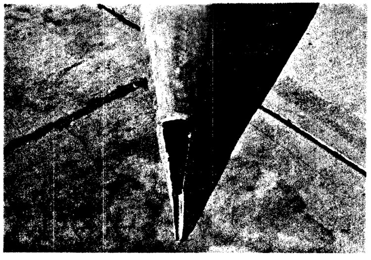
INSTALLING THE VERTICAL FIN
Before beginning this section, the fuselage whould be glassed on the outside, the tailspring support installed, and the Vertical Fin/Rudder combination completed and working. Begin by leveling the fuselage laterally.
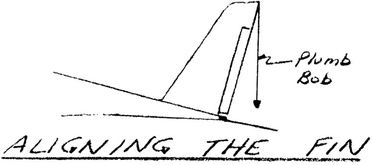
The vertical fin may have trimmed both front and back so that it will fit snuggly into the fuselage. When in position, the bottom of the fin should be resting on the bottom of the fuselage, and the tailspring should be resting against the bottom of the vertical fin reinforcement. When you are satisfied with the fit, check the vertical alignment. If you stand back and eyeball the fin, you probably can estimate within 1 deg. when the fin is vertical. A more accurate way of doing it is to use a plumb bob. Since the fuselage has been leveled laterally, the plumb bob hanging vertically should follow the vertical trailing edge of the fin when the fin is level vertically. Finally, check that the fin tracks straight along BLOO.
Use micro wherever the fuselage and fin join to mate except for the tailspring. At the tatispring, use flox to permanently mount the tailspring.
After mating, recheck the fuselage 1eveling laterally, and then the vertical alignment and tracking of the vertical fin. When satisfied, let cure for one day.
The next task is to make a filet to cover the gaps between the vertical fin and the aft fuselage, it is probably easiest to use several pieces of green and orange foam, 5-Minute them in place, and then sand and contour them to obtain an pleasing shaped filet. Avoid letting the foam get less than 0.3’ thick during the carving process. You can check the thickness with a nail or toothpick like you did when you were carving the fuselage sides. Layup 2 BID on the filet, overlapping by 1” both the fuselage and vertical fin.
Next, layup 3 UNI in a wraparound style around the tailspring area. This UNI strengthen the aft fuselage for the high tailwheel loads.
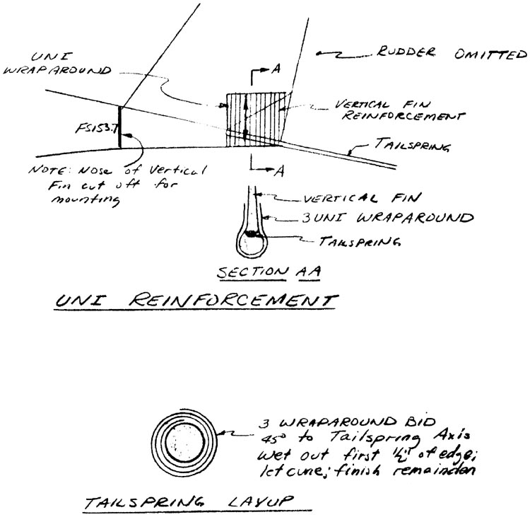
Finally, wrap BID around the tailspring with the orientation at 45 deg. to the long axis of the tailspring. Three times around is sufficient to provide the necessary torsional stiffness for the tailspring.
Peel Ply the joints before quitting.


