Login Form

Q1 Plans Chapter 7 Page 7-14

STIFFENERS

In this section, you will make the firewall stiffener, and the left and right canopy stiffeners. The canopy stiffeners will be used later in the canopy section.

Begin by cutting three pieces of orange foam with the following dimensions:

  1. 1.2” x 18” (Firewall stiffener)
  2. 1.2” x 25” (Lt. canopy stiffener)
  3. 1.2” x 43” (Rt. canopy stiffener)

Mark each piece with the proper name and mark one end of the canopy stiffeners as the aft end.

Before glassing, some plywood inserts need to be located in the canopy stifferners. The firewall does not receive any of these.

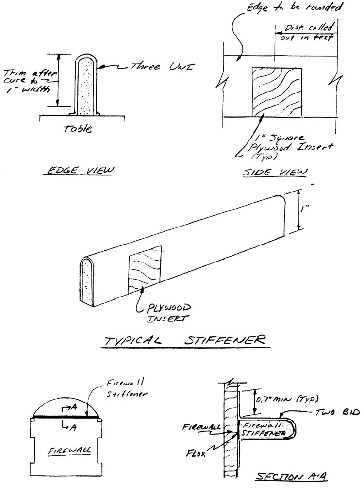
The right side canopy stiffener gets plywood inserts of 1” square at 6.9”,1l.2”, 29.9”, and 34.2” forward of the aft end. Remove the orange foam, insert the inserts with micro, and make a smooth transition with the orange foan.

The left side canopy stiffener gets a 1” x 2” plywood insert 19” forward of its aft end, and 27" forward.

So that the glass will layup around the edge, round one of the long edges of each stiffener.

Set each stiffener vertical on the table, held in place with a few dabs of 5-MIN. The remaining square edge should be the edge on the table. Lay up three UNI on each stiffener, with the orientation running along the length of the stiffener. Since the end resting on the table will be trimmed, you don’t have to worry about the part of the stiffener within .2” of the table.

After the layups have cured, trim the square edge so that the width of each piece is about 1”.

Quickie Firewall Stiffener Installation

Mount the firewall stiffener with two BID as shown. The stiffener is located on the aft side of the firewall (i.e. the cockpit side) and rests on top of the longerons. Use the BID to join the stiffener to the longeron.

Q1 Plans Chapter 8 Page 8-1

BUILDING THE VERTICAL FIN AND RUDDER

The rudder is constructed exactly like the aileron was so review that section on the “Basic Aileron Construction” before proceeding.

Begin by making CS21, which is a 26" long piece of l/2" O.D. x .035" wall 2024T3 Aluminum tubing. Also make CS22 which is a 1" length of 7/16" x .063" steel tube. Find the two CS23 phenolic bearings, and the CSA10 rudder horn assembly.

The hot wired rudder foam core will have to be cut to a 26" length. Save the excess as this will become part of the upper vertical fin. Now, layup one BID over the rudder just like you did with the ailerons.

Begin building the vertical fin by laying up one BID in the rudder slot at 45 deg to, and parrallel to, the trailing edge. After that layup has cured, sand off one of the tails so that the top flows smoothly into the rudder slot. Shape the vertical fin tip to a pleasing shape.


Quickie Vertical Fin Reinforcement

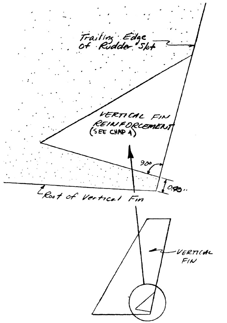
Next, install the Vertical Fin Reinforcement by removing the blue foam where necessary and using micro. The red foam will have to be sanded to obtain the same airfoil shaped contour. Sand the rudder slot into it also.

Now layup one BID over the vertical fin, in the same manner as the ailerons. A second piece can be used for the tip area.


Quickie Rudder Installation

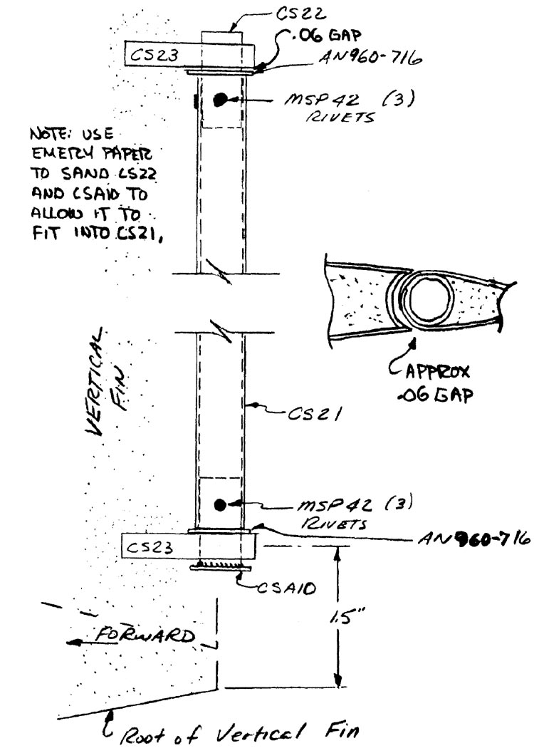
Next on the agenda is installing the rudder. The centerline of the lower pivot is located 1.5” along the rudder slot from the base of the vertical fin. Dry fit a CS23 at that location, and then, using the rudder, locate the other CS23 at the top. The rudder should have about .06” freeplay.

Before mounting the CS23 bearings permanently, you will have to verify proper gap between the rudder and the vertical fin. Insert CSA10 into the bottom end of CS21, and CS22 into the top end of CS21, with the CS23 bearings in place on CS21. After verifying that the rudder horn part of CSA10 is perpindicular to the chord of the rudder, go ahead and drill it in place. Also drill in and rivet CS22 in place.

Review the section of the plans on installing the ailerons, and then mount the two CS23’s permanently with micro, checking the gap between the rudder and the vertical fin. After the micro has cured, layup one BID over the CS23 bearings on each side to permanently attach them to the vertical fin.

To complete the vertical fin, take the excess rudder foam core, make up a foam piece that will fill the gap between the core and the vertical fin, and use micro to construct the top part of the vertical fin. Layup one BID oier the foam to join it to the already glassed vertical fin.


Quickie Excess Rudder Foam Core