Q-talk 156 - Elevator Roll Trim


- Details
- Category: Q-Talk Articles
- Published: Thursday, 20 December 2012 16:55
- Written by Bruce Crain
- Hits: 6338
by Bruce Crain
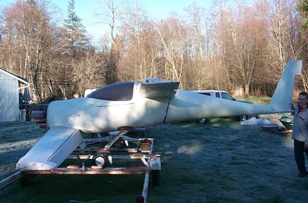
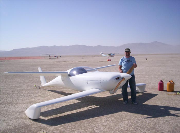
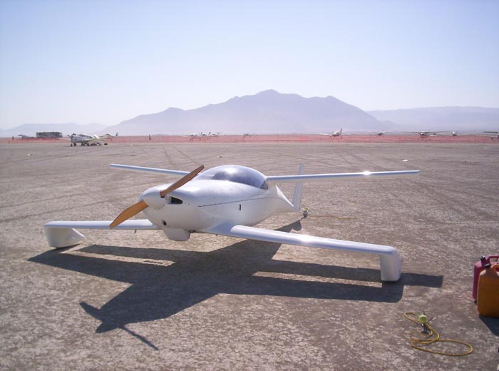
Tri-Q200 N96BJ
I test flew my newest modification on my TriQ 200 today! (November 18, 2012) In the past 2+ weeks I cut out a hole in the top of the main fuel tank so I could run push/pull tubes from the stick directly to the elevator actuator arms. The hole wasn't big but the tubes needed a valley to run in.
 |
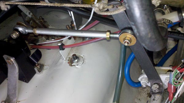
||
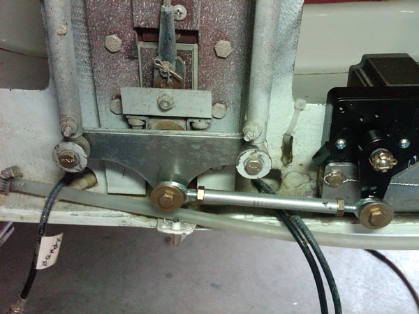
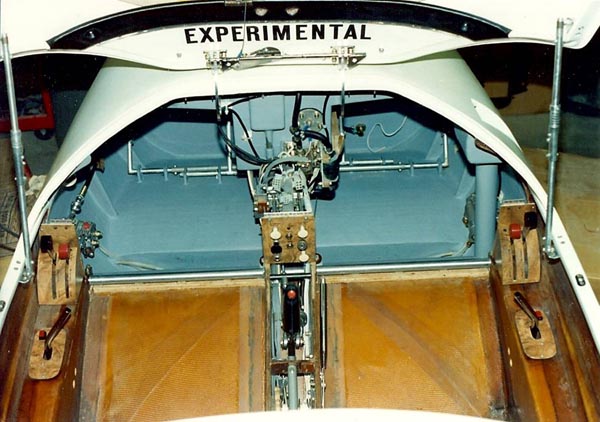
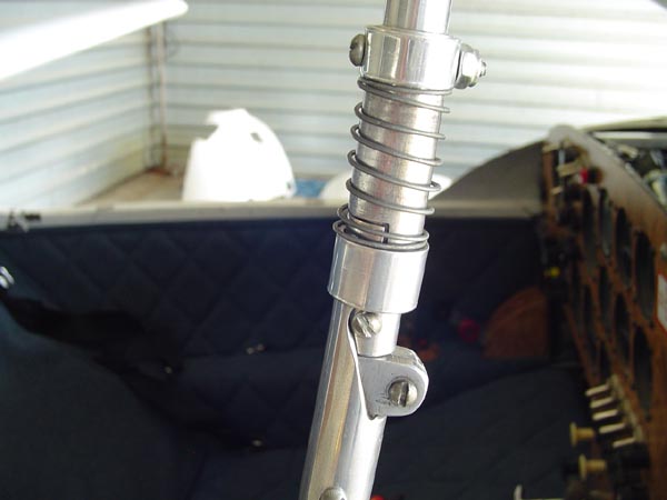
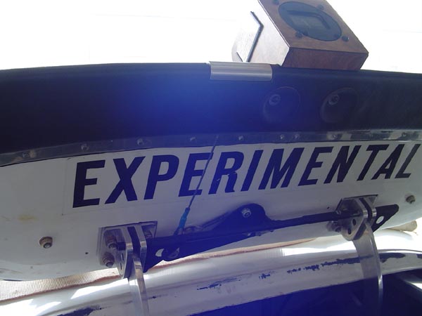
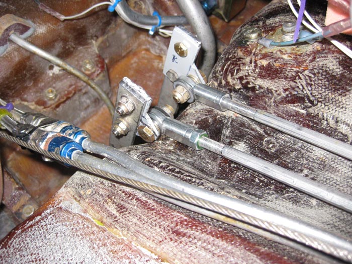
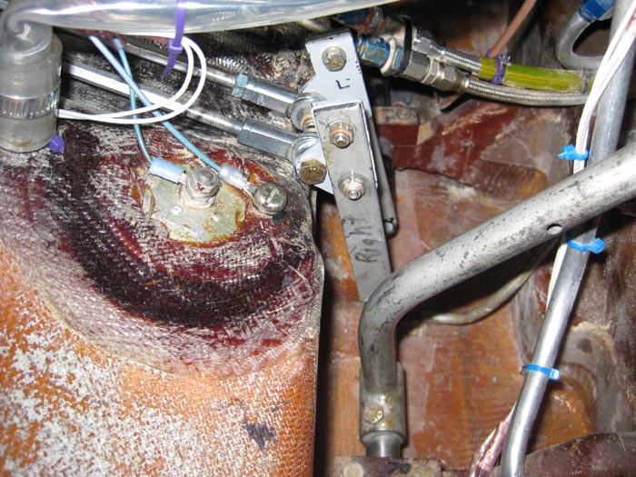
| Forward view of the push/pull and the rod end bearings plus the cut out for the fuel tank to allow the tubes to pass from the stick directly to the elevator actuator arms. | ||
I used 2 turnbuckles with left and right hand treads from McMaster Carr. I lock one turnbuckle down with jamb nuts and leave the other free to turn but which has a limit to keep it from screwing out of the rod end bearings.
 |
||
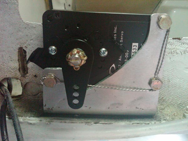
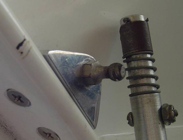
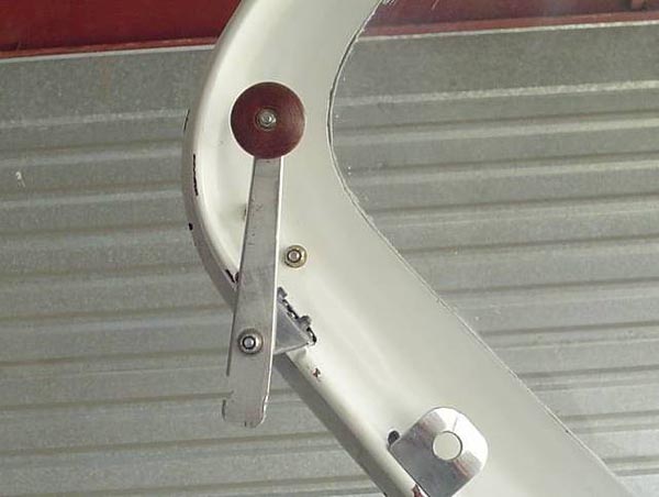
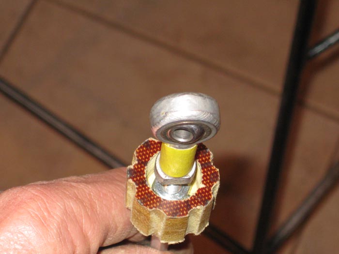
| Rod end with jam nut inside the roll wheel which was recessed to help with limited space in the center console. | ||
My old system used a bungee strap to pull the ailerons over to the light side of the Q. I could see that they added a bit of stick pressure and also looked like they might add some drag especially when I am solo and very left wing heavy (the ailerons were quite remarkably deployed to offset).
 |
||
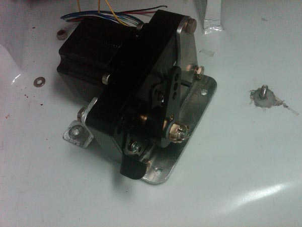
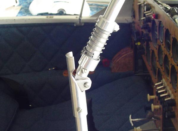
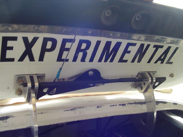
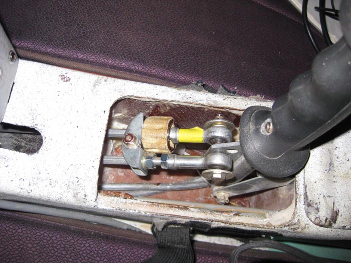
| Left view of the stick and the push/pull tubes with the left tube jammed with jam nut so it will not move. The right tube has the trim wheel to spin for longer or shorter to roll left or right. | ||
The flight today was a much improved TriQ! I may have increased my cruise speed by about 6 to 8 mph. The jury is still out on that as I don't remember exactly what the former cruise was. Only that the old indicated was somewhere between 145 to 147 and I don't remember what altitude those number come from (2300 to 4000 msl maybe).
 |
||
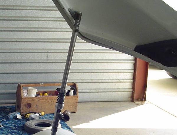
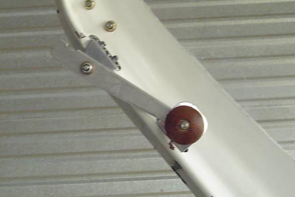
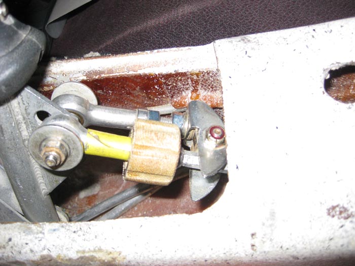
| Stick and trim rolled right. Notice the wheel is further forward to drive the right elevator forward and move the right elevator up and kill the lift for the right canard. | ||
Today the cruise was mostly at 154 mph and that was at 4000' msl. The altimeter was 3007 and temp was around 45 degrees. My airspeed is off about 8 to 10 mph slow at cruise so I figure true airspeed was around 174. I could be wrong but at least I feel I had an increase in airspeed.
The stick pressures were almost surreal as I trimmed the elevator back and forth. Just a little trim and it rolled quite nicely and easily. The handling is much better than adjusting the bungee trim and loading up the system. In the past I worked quite extensively on the sparrow strainers and they are neutral for cruise without the old spring pitch trim. It has been removed and the pitch is lite so the roll trim is not loaded up with up or down pressures on the old spring system.
 |
||
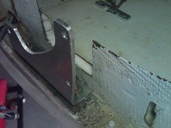
| View of the fore push/pull tubes and rod end bearing from the right side or "Starboard". | ||
All it takes to roll the airplane left or right is one finger on the trim wheel! In the past I have had a bit of slop in the elevator system. When I would do an aileron roll the plane would be out of trim after the roll. So I attacked the elevator torque tubes and actually used 4 large Cherry max pop rivets to help the 3 bolts that held them in place (I know it's going to be really tuff to get them off in the future). Now they are rock solid!
I also (with the help of Terry Crouch's article/interview with the late Dave Richardson and his advice and also Paul Fisher's input) did the mod to the inboard end of the elevators. The mod makes a bit of a rib and also surrounds the tube in the elevator with BID and also Flox. It also keeps any fuel from getting in through the bolt hole access in the top and bottom of the inboard end of the elevator skins compromising the bond with the tube and the surrounding foam. The mod can now drive the entire elevator on the inboard end if needed. Just a bond with the foam and micro was of concern for me.
 |
||
| Cherry max pop rivets added to the torque tubes to alleviate a bit of slop in the system. The bolts had elongated the holes a bit over time. (I know it is going to be a real chore to get them out come annual. | ||
After the test flight I need to adjust the elevators at the torque tubes because the elevators don't come down enough. (The landing payed off at about 90 mph! Whew, good thing I noticed that it took a lot more airspeed to get air born)
So in essence in the last 2 weeks I:
- Improved my airspeed
- Eliminated a safety problem with my elevators.
- Took out all the slop in my elevators. (I did 4 aileron rolls today and the trim was spot on after the roll!)
- Made a roll trim that is solid and easy in action.
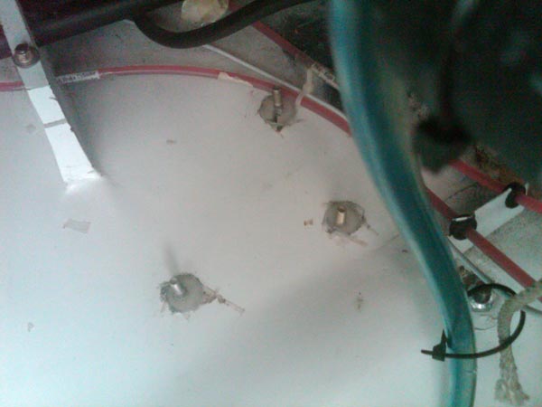
- Cut out the top and re-glassed the bottom fuel tank with a "valley".
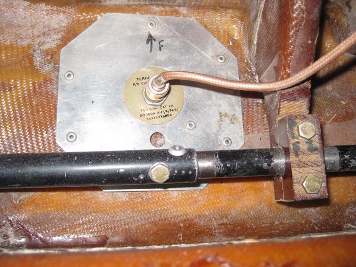
- I had to move the fuel sending unit and the overflow tube a bit to the right to make room for the "valley" in the fuel tank.
- Lessened the stick pressures significantly in roll (Pitch was already lite).
- May have improved the roll rate as the elevators actuate just a tiny bit in sinc with the ailerons plus they are not fighting each other now.
TriQ 200 N96BJ has been test flown and is working as planned after 2.50 hrs of flight. More to come before passengers allowed. The only thing I had to address is the elevator linkage. I didn't make sure the elevator deployed down far enough and when I took off it wanted to stay on the ground. So when I came in for landing I added quite a bit of airspeed. When I landed the Q payed off at about 90 mph so the extra speed kept me from smacking it hard!
I also took the time to add another filter (side by side) to the transfer fuel pump as cutting into the fuel tank produced quite a bit of debris in the main tank. That was after only 2.5 hours of flight. I have 2 pumps for transfer with another filter. So I have 3 filters on board and plan to check them often especially within the first few hours. I found a NAPA 1/4" screen fuel filter which sometimes is visual and sometimes is cloudy in appearance. I like the clear but you can't always see the particles of epoxy debris in the fuel. It is best to either blow them out or just change them (easier).
Has anyone seen "Honey Lamb"?! She probably feels forgotten! But this weekend she had to drive from Enid to Dallas (while the TriQ was down) to spoil our Grand babies and see our son and daughter in law. It is a 10 hour round trip by car (and she drives fast!). In the TriQ 200 it is just a 3 hour round trip! She loves this airplane especially when it comes to seeing her babies!!! ;o)And I got to spend time with my "Baby". Or as Sandy Hoskins says "the fiberglass bit#@ch" (Oh. . . and thanks Sam for always answering my questions over multiple phone calls)
Get 'em done guys! In this day and age, of fuel prices and airspeed, the Quickies just make great sense!!!