Q1 Plans Chapter 8 Page 8-3
- Details
- Category: Quickie Plans
- Published: Sunday, 05 October 2008 01:00
- Written by Dan Yager
- Hits: 2728

RUDDER CONTROL SYSTEM
The rudder control system consists of rudder pedals, 3/32” cable running directly to the tailwheel, and then 1/16” cable running from the tailwheel assembly to the rudder. The 3/16” Nylo-flow tubing is used for cable fairleads.
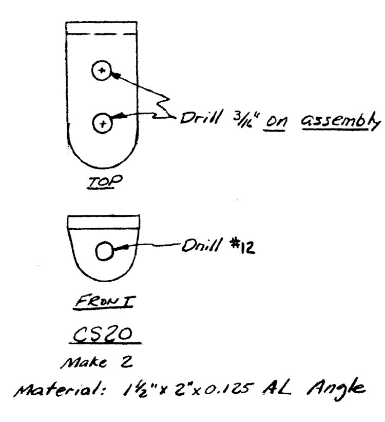
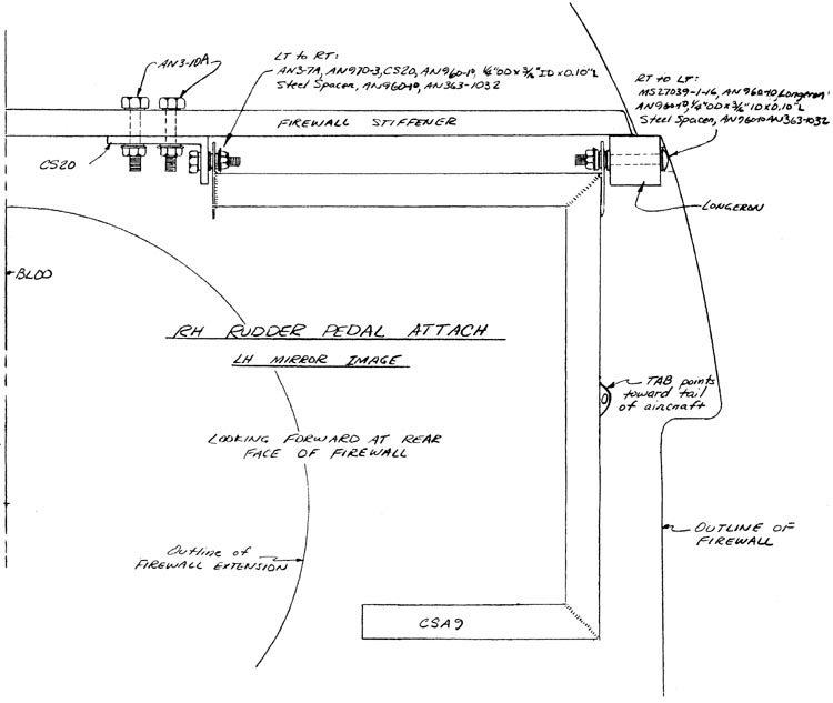
Begin by mounting the rudder pedals. It will be necessary first to make two CS20’s out of the aluminum extrusion. Note the tab on CSA9 points toward the aft end of the aircraft.
The side view included with these plans shows the general routing of the cable. Avoid sharp turns through the fairleads, and at the location where the cable exits the fuselage, position the exit so that the cable will run parrallel to the tailspring. This is to prevent being able to pull the cable at an angle, which would put excess loads on the structure.
Note that the AN115-16 cable shackle is used only with the rudder pedals and the outboard CS24 attachments; the other four points, because of much lower loads, delete the shackle and pull directly against the Thimble.

CONTINUED ON NEXT PAGE


