QuickTalk 23 - Q-2 HINTS
- Details
- Category: Q-Talk Articles
- Published: Saturday, 31 August 1985 07:11
- Written by Jim Masal
- Hits: 3176
From Don Ismari
I have 56 hours on my Q-2 with the old canard and Revmaster engine. Since rebuilding and modifying the airplane after a landing rollout accident (QUICKTALK #18), the airplane behaves much better on the ground. I feel comfortable in it now and have flown it to about 1060 lbs. Climb rate here in Las Vegas fully loaded on hot days, is less than exciting - about 300 fpm. I have been working out engine problems since the airframe problems seem to be corrected. My oil temperature has been running high and the valves are generally closed (no clearance) after progressive checks at 5-7 hr. intervals.
On 9 July 85, I flew the airplane to Hesperia and met with the Revmaster folks. They were extremely helpful and nice to deal with - particularly Eric Schilling, Dick Joh and Alan. They showed me drawings for cylinder head and barrel shrouds which had been provided to QAC 2 years ago and are required in addition to the baffling. I have made these changes and the oil is running cooler - not there yet, but an improvement.
Revmaster wants me to keep track of the valves with the shroud fix and we will go from there. Eric told me that my air intakes were not efficient even though they were built to plans. I can see his point. Note drawings:

QAC's plans make the air bend and turn too many times. Eric recommends the intakes be right next to the spinner so the air will go straight in. I haven't made this change yet, but he feels it could possibly help my overheat problems and maybe the valves too. Eric prefers the "smile" inlet but he didn't say which is best. I'm on the third set of heads on my engine (only 56 hrs. TT) so I hope these problems will work out.
Controlling the ground angle of attack in a measured fashion helped me the most in correcting the bad directional problems I'd been having. The airplane is so much better now that I can hardly believe it. However, I'm not positive about this but it is one of the easiest changes to do.
CONTROLLING GROUND ANGLE OF ATTACK (GAC)
With your airplane in a ready to fly condition and preferably fueled up, make a template of at least one airfoil (preferably 2: main wing and canard) at BL 50

Cut the cardboard to fit pretty well around the canard and wing at BL 50 (one side or the other). Use some tape to protect the surface and then jam Bondo into the cracks in an effort to duplicate the shape of the airfoil exactly. When it is cured, put the airplane on a level surface and jack up the tail to a flight level condition (such as you do for the weight and balance process). Mark a level line on each of your templates using a level, then put the airplane's tailwheel on the ground and draw in another level line on the template in this attitude. The angular difference between the two level lines is your ground angle of attack.
When my airplane was really squirrelly on the ground, I suspect I was at about 10 degrees GAC but I broke the airplane before I measured it. Right now my ground angle of attack is 8 degrees and it sure makes an improvement to my ground handling qualities.
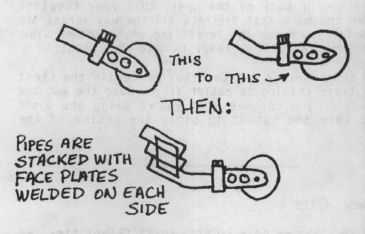
I got to 8 degrees by welding pipes to the original tailwheel fork. First the fork was bent to make the castor angle vertical and eliminate some instability. We then welded cut sections of tubing on the front end of the fork to lift up the rear end.
MOVING THE MAINS FORWARD
This is a big job. If you have directional control problems, I'd try the others first and see if this is really required. Originally my axles were at FS 39.9. They are currently at FS 38.0. You not only have to move the wheels but also the brakes and the holes to accept the brakes if you do this. Re-alignment of the wheels is touchy but doable if they were put in properly in the first place. An easier way to do this is by not following the plans when you are building the wheel pants to the canard. Make measurements of your own and get the axles where you want them (fore and aft) with reference to the canard's leading edge.
To move the mains forwards, flip the airplane on its back, remove the wheels (before doing this, mark level lines at the main wheel axles with the airplane sitting at rest). Bondo a piece of aluminum tubing (axle material about 3/8" long to the end of a mixing stick:

Determine how far forward you want to go and drill a hole at this distance on the mixing stick (distance = d). Push the Bondoed pipe into the old axle holes and align the hole drilled into the mixing stick along the previously smaller than 1/4" - a long one which would reach across is best. Follow this up with a 1/4" long drill and drill both sides of the pants in one pass.
On the outsides of each wheel pant, remove skin and foam to the inside skin (4 places). Make 4 plywood pieces (LG 4's) and remove enough outside skin and foam from the inside pants (2) to be able to shift the LG 4's. Enlarge the inside (2) pant holes to about 3/8". Make up 2 pieces of 1/4" OD tubing long enough to span across the pants with 3-4" on each side. Grease these tubes and mix up some flox. Flox where the skin and foam was removed (4 places) and with the LG 4's on the pieces of 1/4" tubing.
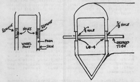
Use the tubes to sight in the axles as explained in the plans. When sighted in, make sure nothing moves during the cure. My axles are zeroed in on one another. Gene Sheehan said to use toe out and Scott Swing said to use toe in. I put them in neutral.
When the above is done, you'll find that your wheel won't fit in the well. To accommodate the wheel, the pant has to be redone. I sawed out the front of each pant and in the process filled in the old brake caliper cutouts and installed new cutouts forward to match the new position of the wheels.
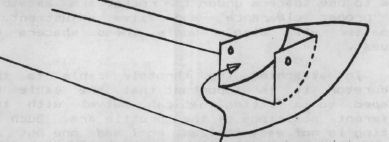
Foam was fitted to the cutout -- and shaped into a new leading edge as well as to accommodate the wheel and tire. Don't forget to put in the UNI stiffners and cover all around with 2 BID.
EXTENDED RUDDER AREA
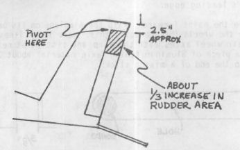
All I did here was to cut out and reposition the top pivot and enlarge the rudder by:
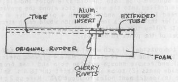
The insert tube and rivets were used to help stiffen the two-piece torque tube. A foam block was dry microed to the end of the rudder. When dry, it was sanded to shape using the original rudder part as a form for shaping. The shaped foam was then skinned with 2 BID overlapping onto the sanded original rudder. There is an unnoticeable bulge at the overlap and I had to sand out the slot a bit to get required clearance.
From Saylor Milton #2484
Notes on Revmaster R2100-D installation:
1. If your engine has been in storage for some time, the FIRST things you want to do is to remove the heads and inspect the condition of the valves. I found the valves of my engine to be badly rusted with rust flaking off. As iron oxide rust is a harder substance than iron, the flakes could cause scoring of the cylinders. Revmaster will send you detailed instructions on head removal and replacement on request.
2. It simply is not possible to install or remove the "A-R" exhaust system when all pipes are welded together. This is especially true if you try to use the supplied studs instead of bolts to attach the exhaust flanges to the heads. I had to cut the exhaust pipes from cylinders 1 & 3 and welded a pair of flanges in the middle of these pipes so the exhaust system could be easily removed by unbolting the flanges. Use a liberal amount of anti-seize compound on all studs and bolts on the exhaust system.
3. If you install the new 75 HP heads, you may have to use spacers under the rocker arm assembly for proper clearance and valve adjustment. Revmaster will also supply these spacers on request.
4. In attaching the throttle cable to the carburetor it is important that the cable be clamped to a fitting that can swivel with the different positions of the throttle arm. Such a fitting is not easy to find, so I made one out of an old, heavy-duty radio volume control using it's shaft and threaded sleeve. (The fitting is not easy to draw or I would have enclosed a sketch.)
How to make stringers for the "sparrow strainers" on the LS-1 canard:
Use the supplied pattern for the stringers to cut out four molds in 1/4" white sheet foam. Enlarge the molds slightly to allow for sanding and trimming. Grease the molds lightly and place them on a layer of BID. This should be done on top of a sheet of waxed paper or plastic. Mix up a batch of flox with some micro added to make it smoother. Allow to stand for a short time to allow all bubbles to rise. Pour the mixture in the foam molds to slightly overflowing. Place another layer of BID on top and squeegee the mixture into it. When cured cut away the molds and sand all four stringers together. These will be very strong and much easier to work with than if made with plywood.
From Richard Kautz #2850
1. To shim the disc portion of the disc brakes, purchase an inexpensive set of feeler gauges and cut off what you need with a pair of tin snips. For really fine adjustments, use .001 brass shim stock. Torque the bolts to 65 inch pounds.
2. MOUNTING THE CANARD IN ONE STEP
This method took me less than one hour and required no fitting at all. It also mounts the canard as low in the fuselage as possible.
Begin by leveling the fuselage in all directions with a water level. Measure across the "flat" at the center (leading edge) of the canard. Add 1" to this measurement and measure across the firewall until you find this measurement. Make sure the line you draw across the firewall is level. Now, using your water level, transfer this line to the sides of the fuselage extending 20" behind the firewall.
Next, take the BL 15 canard hotwire template and carefully trace it onto a piece of light shirt cardboard. Take a compass and close the back of the template where the spar is. Remove the area where the tails are and carefully connect the spar and the upper and lower surfaces of the canard template. Don't forget to draw the level line on both sides of the template!
At the fuselage, line up the level line on the template with the level line you previously drew down the side of your fuselage. Don't forget to leave about 3/8" at the leading edge for the thickness of the firewall. Carefully trace around the top surface of the canard and stop when you get to the level line at the back of the spar. Now measure from the front face of the firewall along the level line to the back of the spar. Roll your fuselage upside down and mark that distance all the way across the fuselage until you reach the level line on the other side. Connect the dots and you're ready to make the cutout.
My canard and fuselage fit together perfectly the first time. Two tips: cutting is easier if you have the mag box cutout made so you can see what you're doing and don't forget to save the cutout to close the bottom of the fuselage.
From Ed Lacy #2158
As of May 20, '85, we have 20 hrs. total flight time. We seem to have got out of the rut of dinging the airplane. We made a change in canard incidence, which helped some, but what really got the plane to handle well on the ground was raising the tail until we had 8 degrees on the main wing. We think that the tail bouncing was caused from the wing stalling and then flying again.
Anyone need help, call the AIR PLANE FACTORY Sat, Sun or after 5 pm during the week at (217) 422-4950 or my home 423-1684 in Decatur, IL.
From Bruce wood #2365
Noise, uneven braking, pulling etc. from your disc brakes? I copied this solution from another builder. I floated the disc and locked the caliper as follows:
1. Remove the brake standoff from the wheel and drill out the six holes with a 5/32 drill. Drill all the way through the standoff.
2. Use a 3/16 drill to bore out the holes to abut 5/16 deep to receive the unthreaded portion of the AN3H-10A bolt.
3. Thread the lower portion of the hole with a 10-32 tap.
4. Make 12 5/16 in. long spacers out of 1/4" bushing stock.
5. Enlarge the 3/16 holes in the disc with a 17/64 drill.
6. Safety wire all bolts and mount the tire assembly on your plane.
7. Lock the caliper by using washers and shims so that the pucks make even contact with the disc. While doing this, block the disc from moving with small wooden wedges.
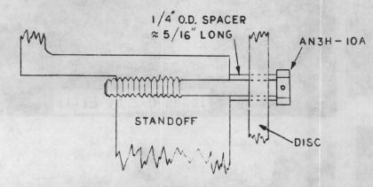
8. The disc should float smoothly on the 1/4" spacers.
After making this mod on my Q-2, I was shocked at the improved braking action.
From Jan Bowman #2121
My Q-2 is complete and officially known as N5585N. A couple of last minute changes were made that might interest builders.
1. The elevator trim suggested by QAC was scrapped and a gear-worm trim installed instead. This eliminates the slippage problem and gets rid of the nylon line Mickey Mouse arrangement.
2. I moved the fuel line discharge from the upper tank to the left rear so the shut off valve is easy to reach from the left side and the filter is easy to see.
3. I installed an aluminum bracket on the oil cooler to hold the throttle cable its full length of the cooler and held on by the two bolts that hold the cooler to the engine.
I found that start up of the Revmaster must be done carefully as the carb will flood within 10 seconds if you open the mixture control without cranking the engine. My procedure is to open the fuel valve, set mixture full rich, wait 2 seconds and crank the engine. If it doesn't start within 5 seconds, pull mixture to cutoff, wait 10 seconds, crank engine then open mixture when it catches.
From Herb
In the Q-2 baggage area behind the seat, we cut out the center support of the seatback bulkhead and made it removable by means of bolts. This allows us to get larger objects into this area without losing the bulkhead's strength.
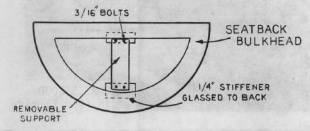
From Saylor Milton #2484
Hint for modifying or resculpturing the engine cowling:
I suggest the following method to make a carb air intake scoop or to enlarge your cowling to clear the exhaust system, vacuum pump, etc.
When you fit the cowling to the engine, cut a hole or slot in the cowling for the protruding object to stick out. Remove the cowling and tape up the hole from the inside with Mylar packaging tape or duct tape. Pour X-40 foam on top of the hole (outside of the cowling) and allow to set. When stiff, remove the tape from the hole and from the inside, smoothly dig out enough foam to clear the protrusion, but leaving a shell of foam around it. Next, laminate 2 BID inside the foam shell, again making sure it clears the protrusion. After the laminate cures, remove all of the remaining foam and sand the fiberglass shell fairly smooth. The next step is to pour a new batch of X-40 form on top of the new bulge and when cured it is sanded to blend in to the remainder of the cowling. When you are satisfied with the shape, paint with wet micro, allow to cure, do a final sanding and laminate with 2 BID.
You can order a PDF or printed copy of QuickTalk #23 by using the Q-talk Back Issue Order Page.


