Q2 Plans Chapter 14 Page 14-06

- Details
- Category: Q-2/Q-200 Plans
- Published: Wednesday, 17 May 2006 15:05
- Written by Quickie Aircraft Corporation
- Hits: 2804
|
..... At BL00, a common attachment is used. The plywood should be about 2.4" x 1.5" and is beveled to form an A-frame arrangement, so that the aluminum extrusion can again pull off at about 45 degrees. The 7 BID is again laminated in place with the 0.75" MIN overlap onto the fuselage. Next, in order to close out the front and rear parts of the 'tent', carve some urethane for two 'plugs', one on either end; these are installed after the extrusion is per¬manently mounted so that the AN525-416R14 screws do not need to be accessed. The plywood was made long so that even with the extrusion in place, there will still be room to laminate 3 BID around the plugs up onto the previous 7 BID lamination with a minimum overlap. Finally, install the seatbelts themselves. The extrusion length for both inboard and outboard pieces is a nominal 1.3". When finished, this BLOO mount should be closed in, rounded, and have glass lapping onto the fuselage inside skin in the four directions. 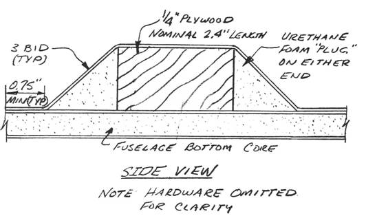 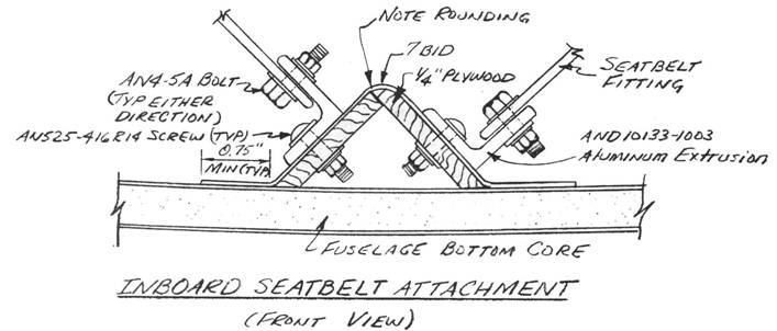 ..... Now is a good time to install the shoulder harness assemblies permanently to their attachments. Since each occupant has a Y-harness arrangement from one bolt, there will need to be two slots per side placed in the seatback bulkhead to allow the actual harness to come through into the cockpit. Sit in the cockpit to determine best where these slots should be; they should be no larger than necessary, and should have a glass-to-glass bond lamination around the slots. COCKPIT CONSOLE ASSEMBLY
..... Now is a good time to install your center console and the two side consoles in your fuselage. The accompanying sketches show the locations. .....Lets begin with the center console, the centerline of which should be on BLOO. To gain more hip room the sides may be angled toward BLOO as they go down. The top center console piece is not installed until after all of the control stick mounting and rigging has been accomplished, but it can be used "dry" to help mount the center console vertical pieces. Remember that the glassed side of those pieces is the side not visible after assembly, i.e. the side nearest BL00. Two cut¬outs will be necessary for the seatbelts to clear the pieces. Use flox along the bottom of each piece to attach them to the fuselage, and laminate 1 BID on the inside lapping onto the pieces and the fuselage a minimum of 1 inch. Do not glass the outside faces of the two center console vertical pieces until after the top center console piece has been permanently installed. The 'kink' is achieved with a saw cut into the foam (not glass) and beveling the foam so that the piece can angle upward. 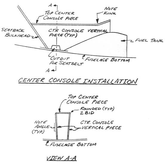 |
||||
CONTINUED ON NEXT PAGE |
||||
PAGE
14-6 |
||||