Q2 Plans Chapter 14 Page 14-09


- Details
- Category: Q-2/Q-200 Plans
- Published: Wednesday, 17 May 2006 15:05
- Written by Quickie Aircraft Corporation
- Hits: 2935
|
..... Once that lamination has cured, trial fit the control stick, the QCS3 spacer, and the CS2 longitudinal aileron torque tube together so that you can locate the CS4 bearings back at the FS94 bulkhead. Be careful to avoid binding. The CS4 bearings should be located on BLOO at about WL14.5. Note that 2 BID and flox are used to attach each of the CS4 bearings to the bulkhead. .....Once those laminations have cured, you can assemble the control system as shown. Remember, the stick must be smooth and free in the pitch and roll directions. Also, the fore and aft travel of QCSA2 must not exceed 0.03", as shown. . .....Work slowly and carefully, being sure not to elongate the holes you are drilling for the various AN3 bolts to connect everything together. Keep checking to make sure the control system remains free and smooth. There is little worse than a fine handling basic aircraft with a very stiff control system. .....The AN3-12A bolt to connect CS2 to QCSA2 will require a hole drilled in the console. This hole can be left open for future access, or closed back up again. Please note that the control stick with neutral aileron is canted slightly toward the pilot for better stick/hand geometry. .....CS5, CS12, and CS13 are made from 1/2" O.D. x 0.035" wall 2024T3 Aluminum tubing. The proper lengths will have to be determined upon installation. Don't forget the length taken up by the rod ends and AN490HT8 adjustable threaded rod ends. Each push-pull tube system has one of the adjustable rod ends to allow for small errors in properly sizing the push-pull tubes for length. You must have at least 2 threads of the adjustable threaded rod ends screwed into the rod ends to be safe. It is recommended that you set up your systems so that the adjustable rod ends are at midtravel, to allow for future adjustment, particularly with the ailerons. .....Use your aileron rigging template and your elevatol rigging template to assure that you obtain the proper amount of travel in pitch and roll. Using wood bonded in place, make control limit stops both between QCSA3 and the fuselage bottom, between Q2CSA8 and the canard shear web, and between QCSA1 and QCSA2 to limit surface travel to the proper limits. DO NOT HURRY THIS SECTION it is too important an area to make mistakes in. .....The stick grip is carved out of Balsa wood and attached to QCSA1 with epoxy., Once your aileron and elevator control systems are functioning, climb into the cockpit and spend 5 minutes playing fighter pilot. Then get back to work, or you'll never finish your Q2. 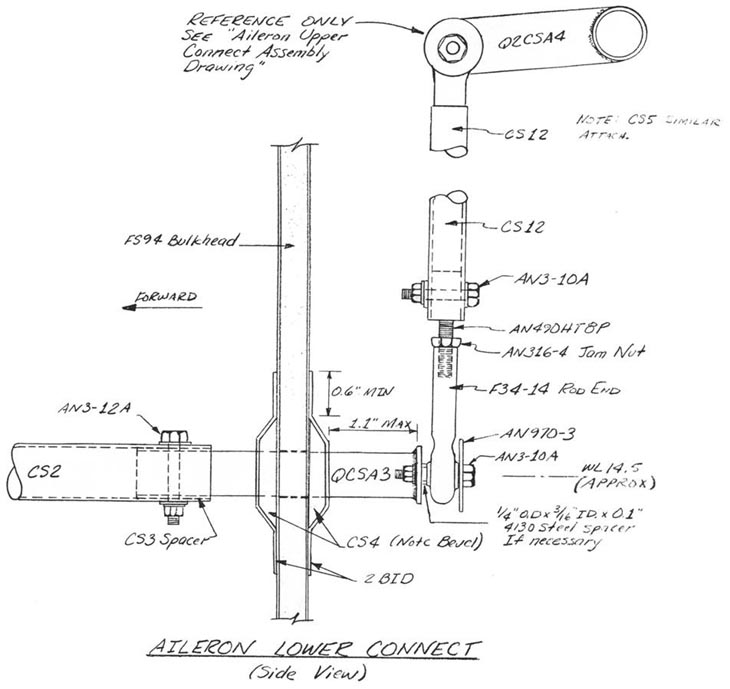 |
||||
PAGE
14-9 |
||||